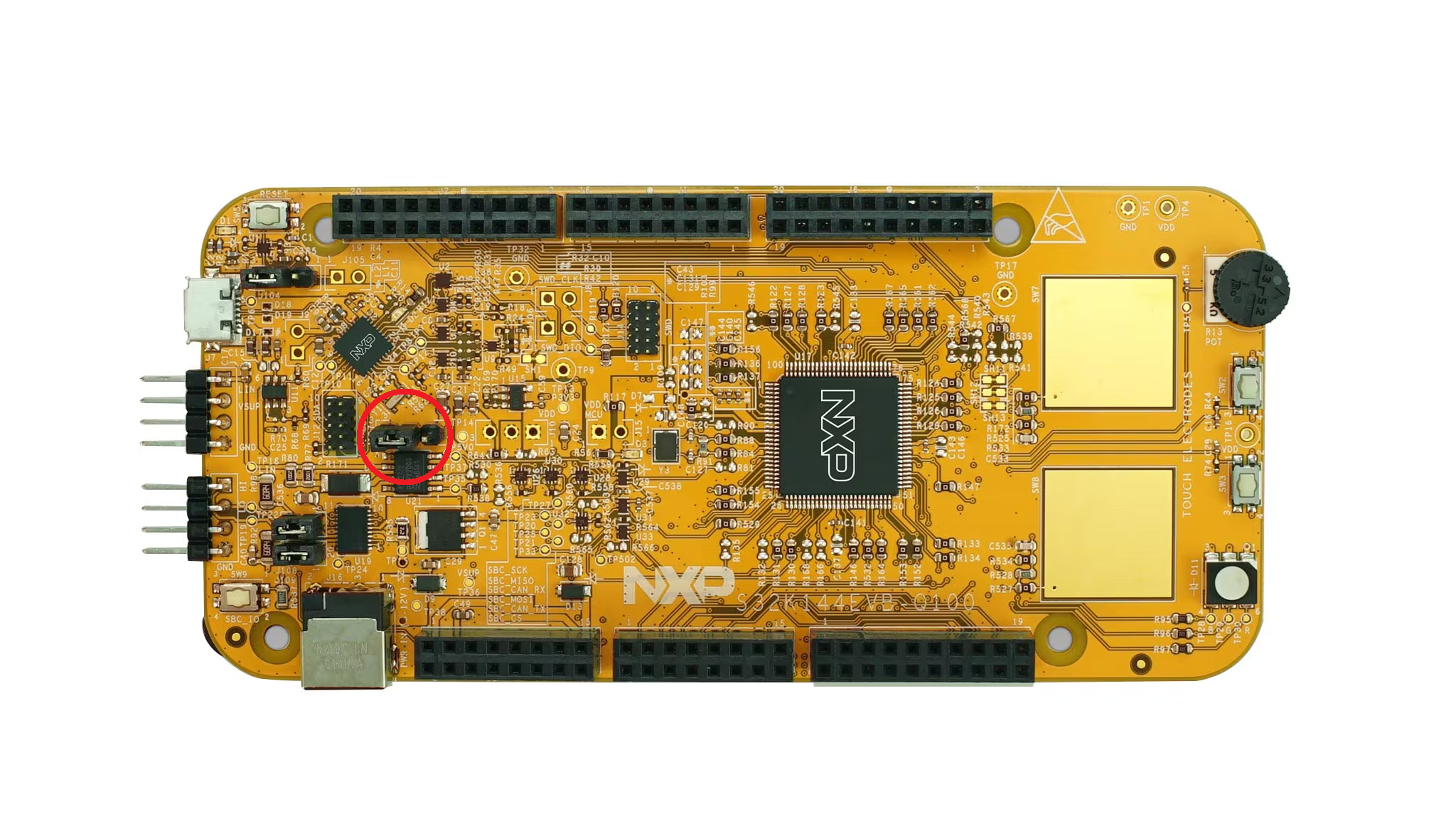
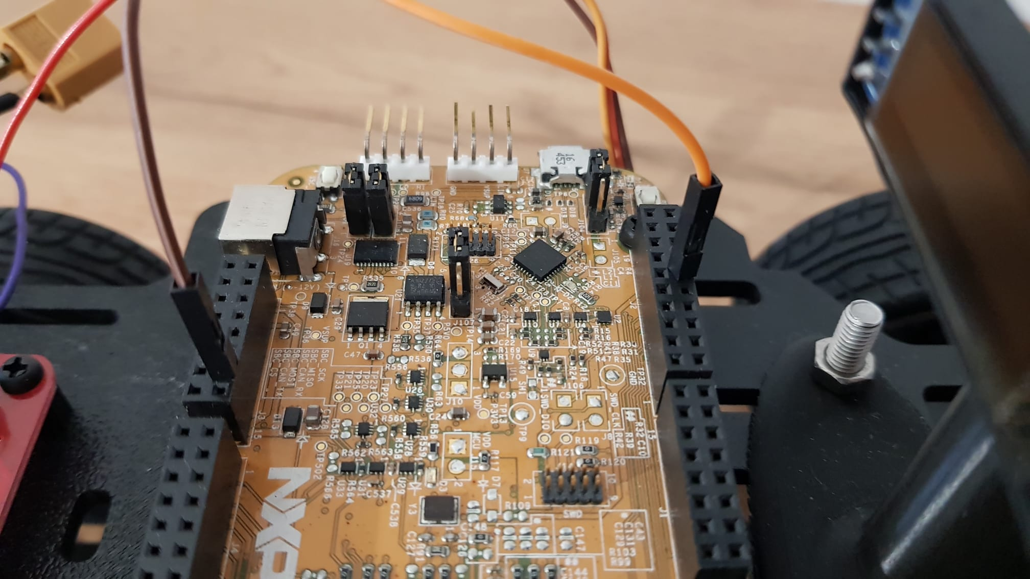
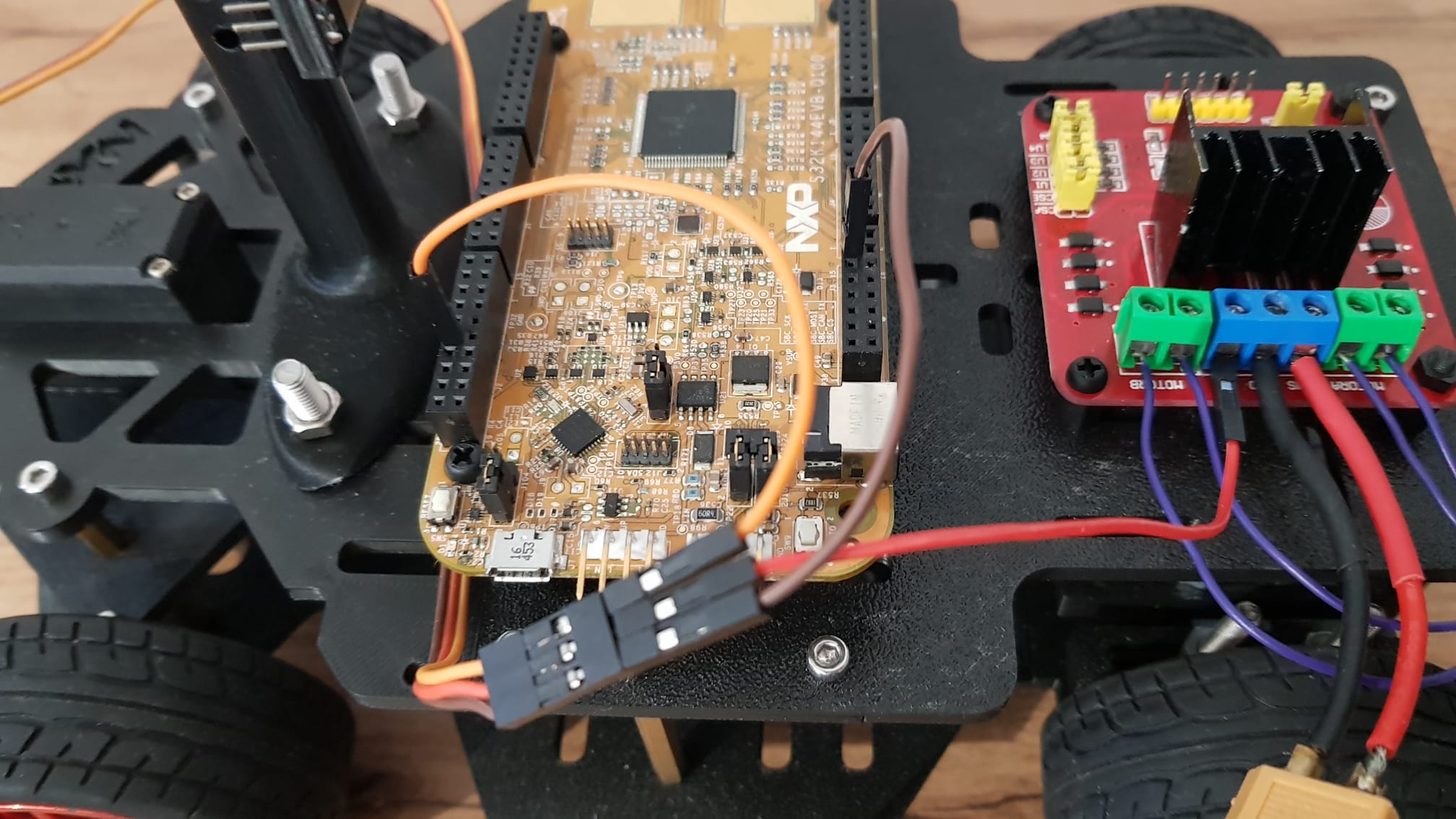
Power selection jumper highlighted. Micro usb power is selected
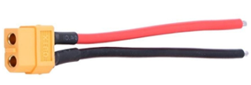
XT60 passthrough with dupont adapter
.jpg?alt=media&token=0d3d9b95-9075-46ac-8b0c-7cbeec872d27)
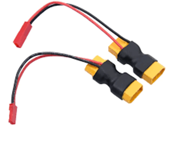
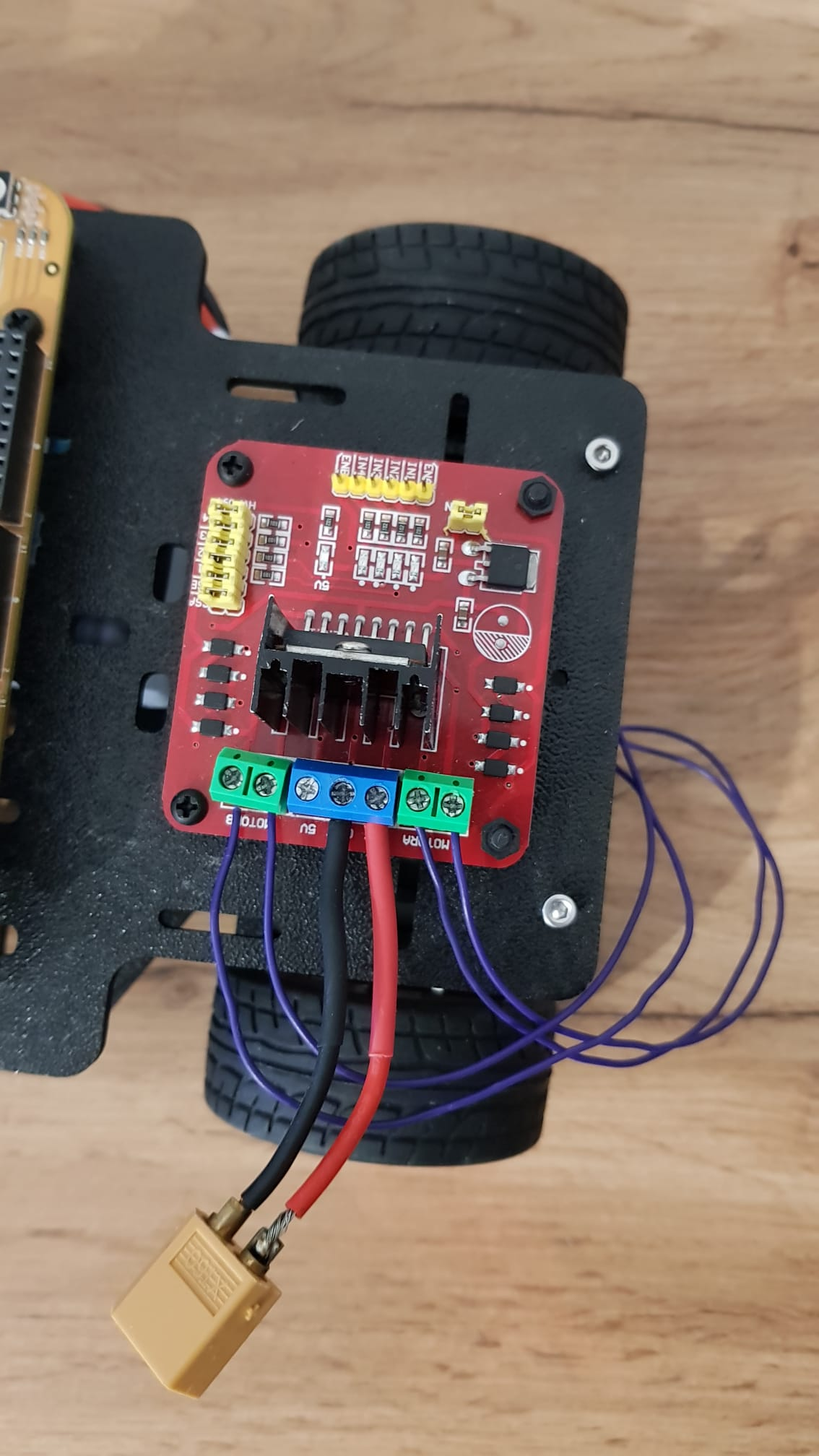
Hbridge power adapter
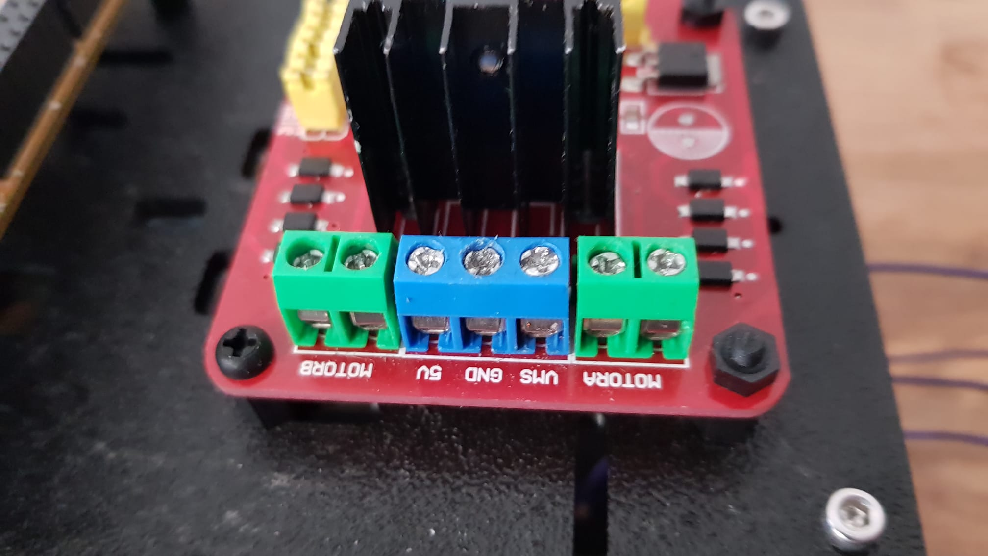
Hbridge ports
Motor cables
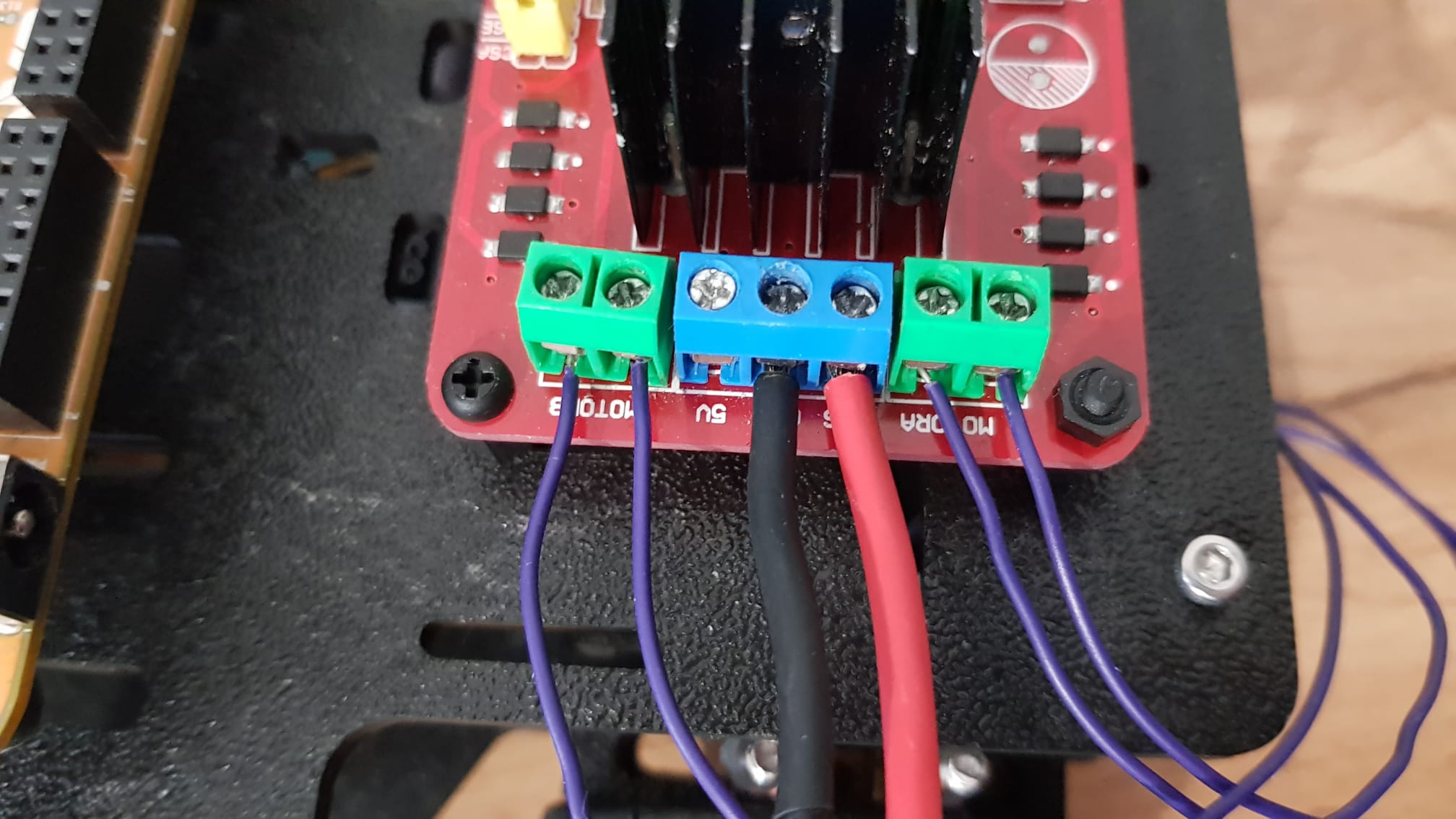
Motor cables connected
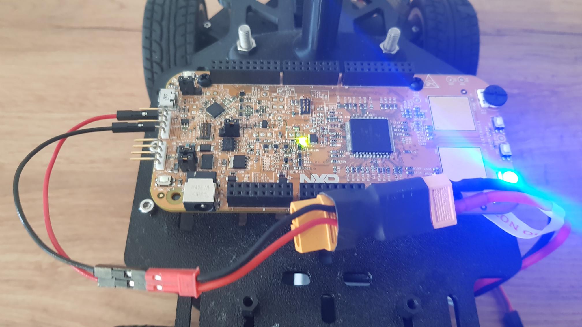
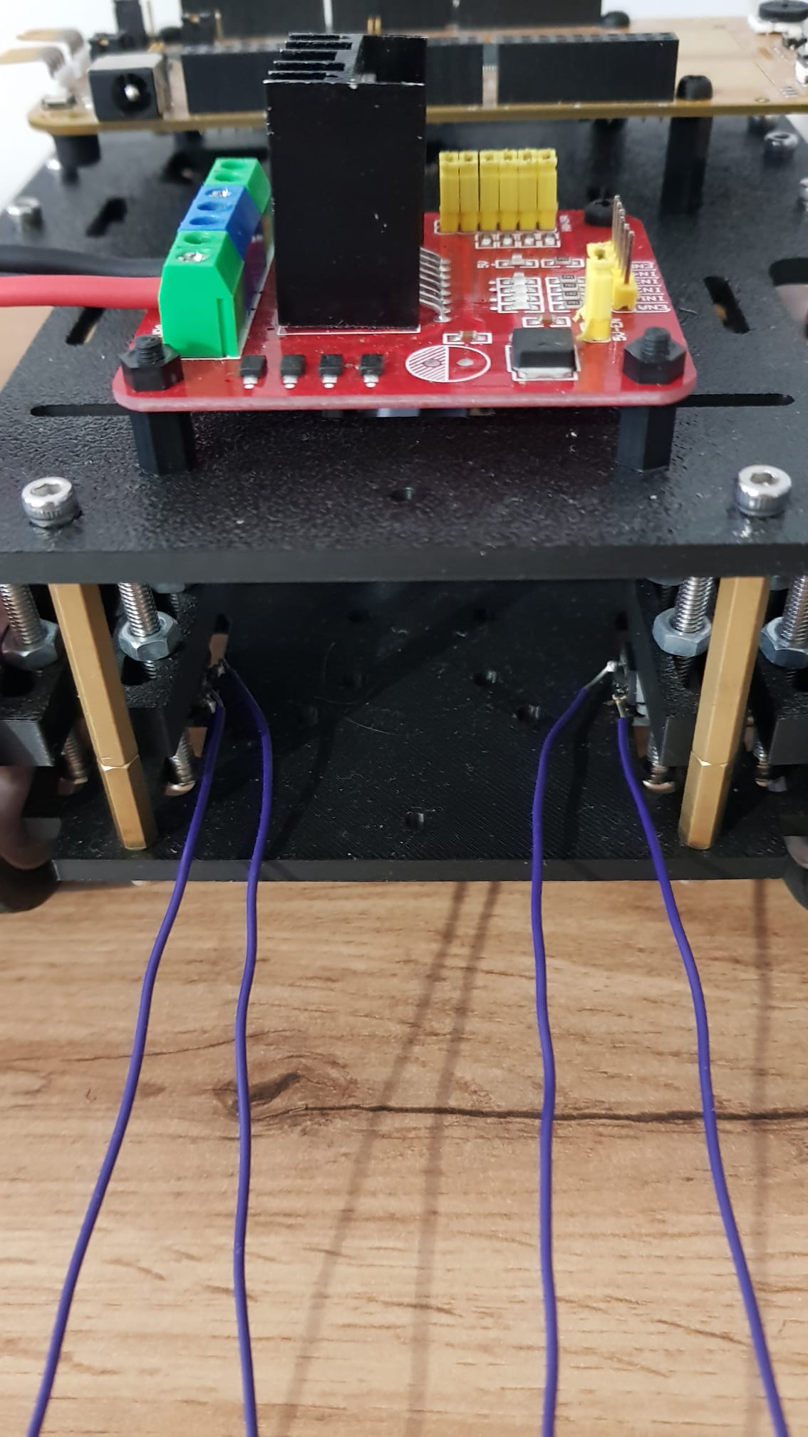
Final result
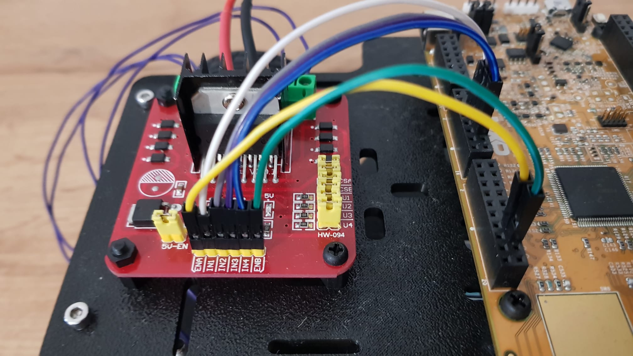
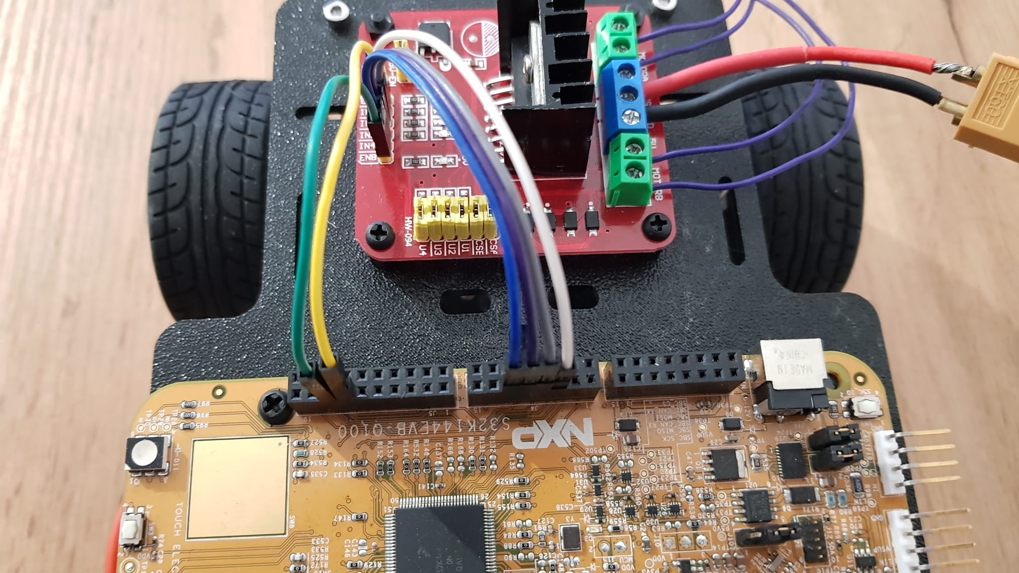
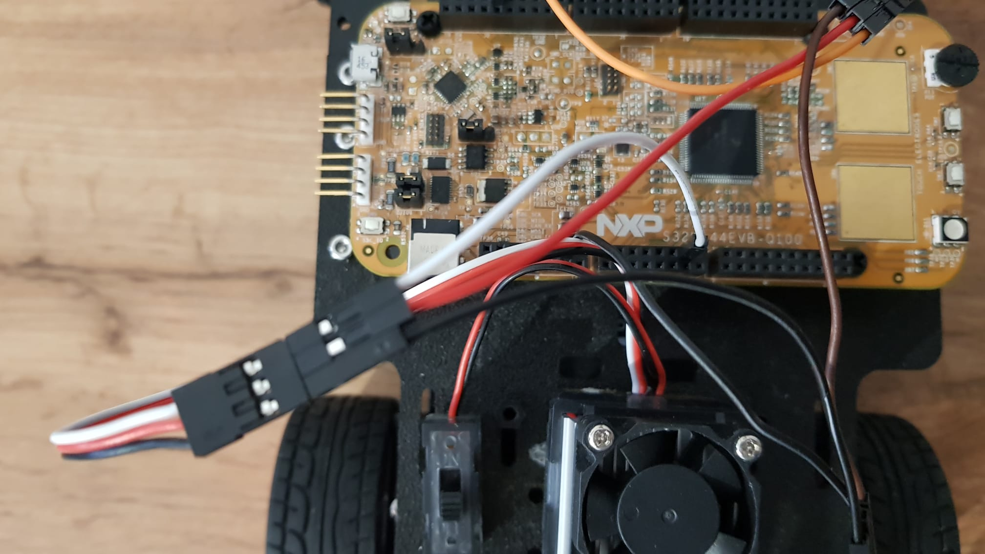
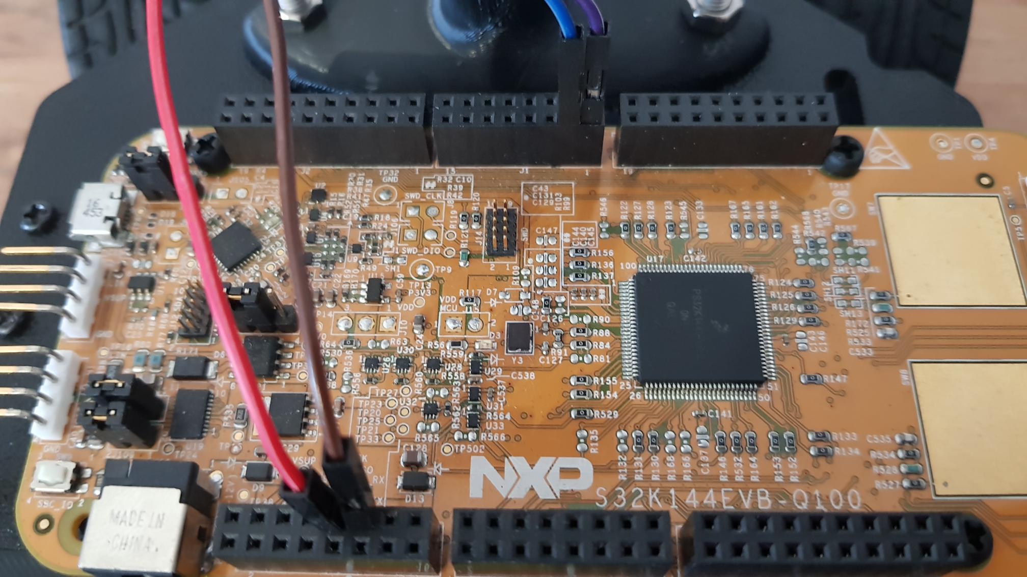
Pwm and ground wires connected to the board
Power wire connected to the H bridge
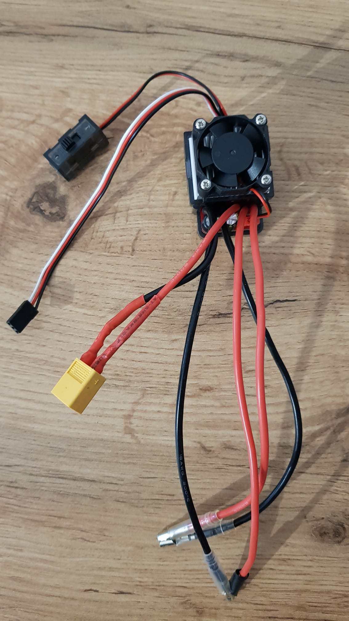
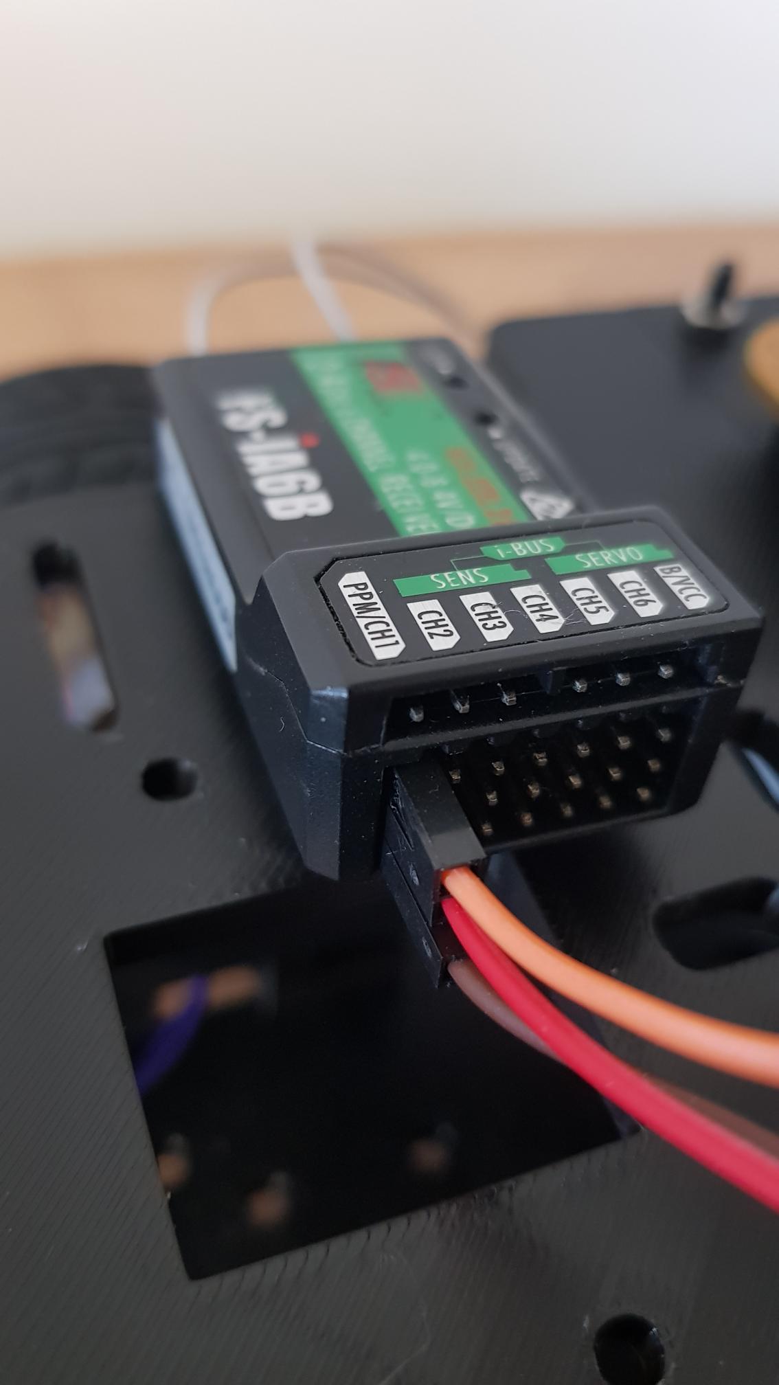
ESC with connectors for two motors
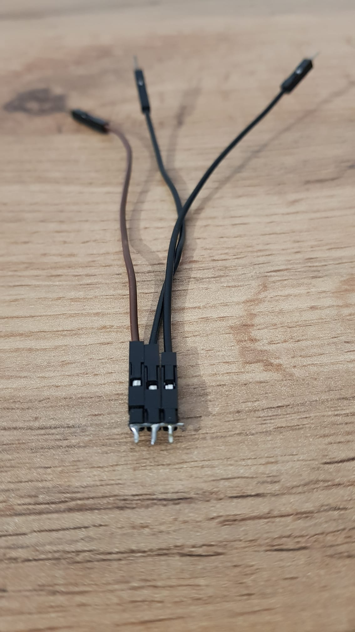
Connecting the three grounds together in the male header with a wire soldered across it
Two grounds connect the ESC and Servo, the last one will go in the microcontroller.
ESC connections
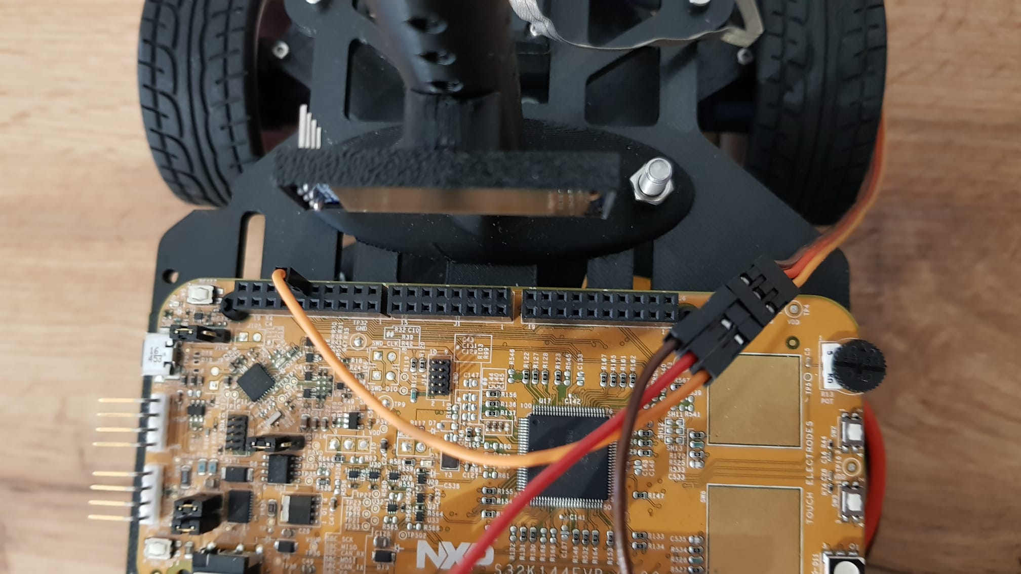
Servo connections
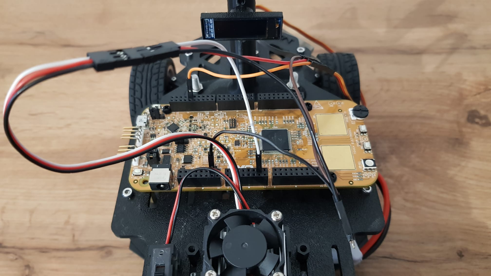
All connections
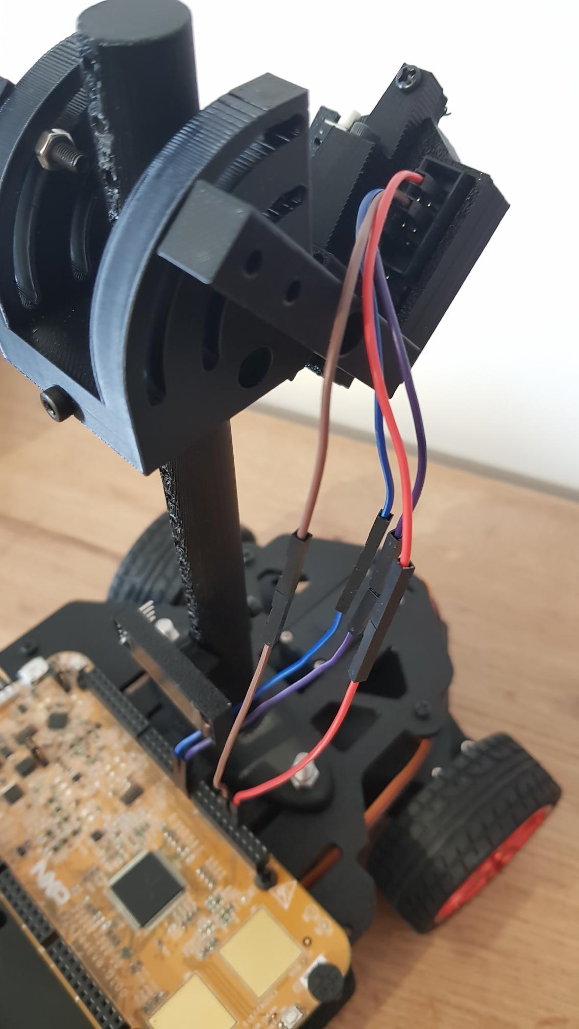
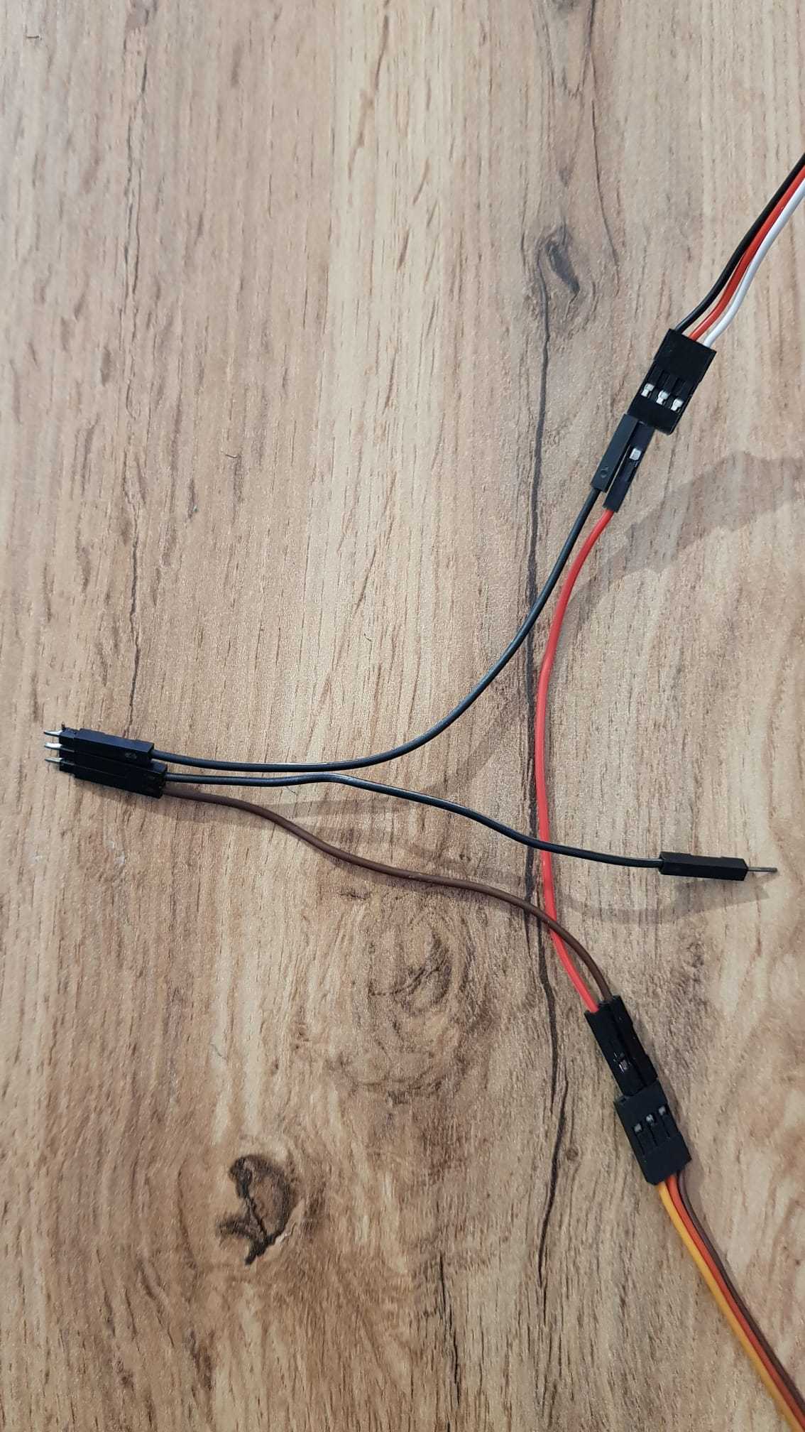
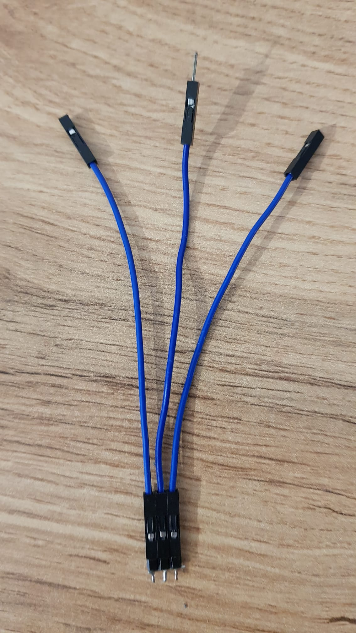
Daisy chained jumpers
.jpg?alt=media&token=da7af0fc-9c71-40e0-bb7d-2695c53f1f6e)
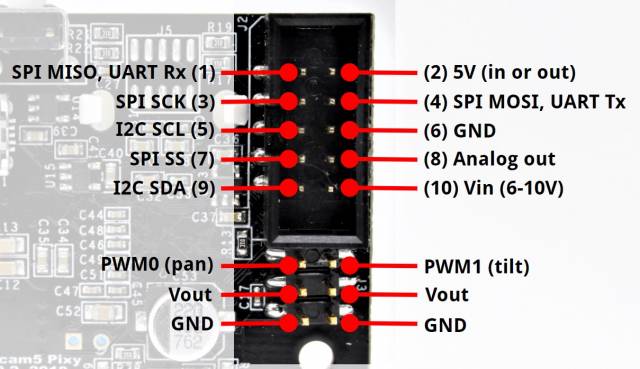
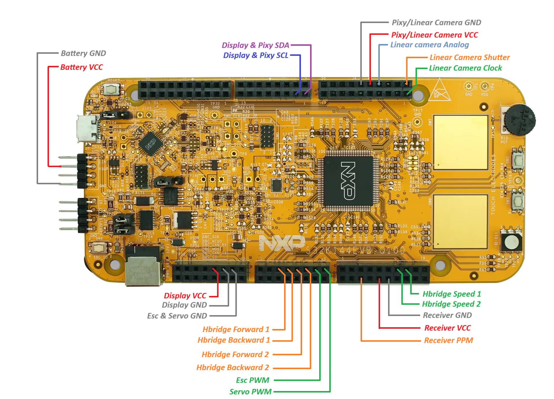
Pixy pins documentation
.jpg?alt=media&token=f8eb787e-2ea8-4acb-bfd7-d37f956e16c1)
.jpg?alt=media&token=a44c8cab-a9d2-4fd6-be34-d560cb745235)
.jpg?alt=media&token=101f182e-301d-43c6-99fb-4d977f5f61d3)

The 3-pin header with a soldered wire across it
Jumpers connected to the header
.jpg?alt=media&token=33f802fc-bb35-4df8-a9c9-297435388d53)
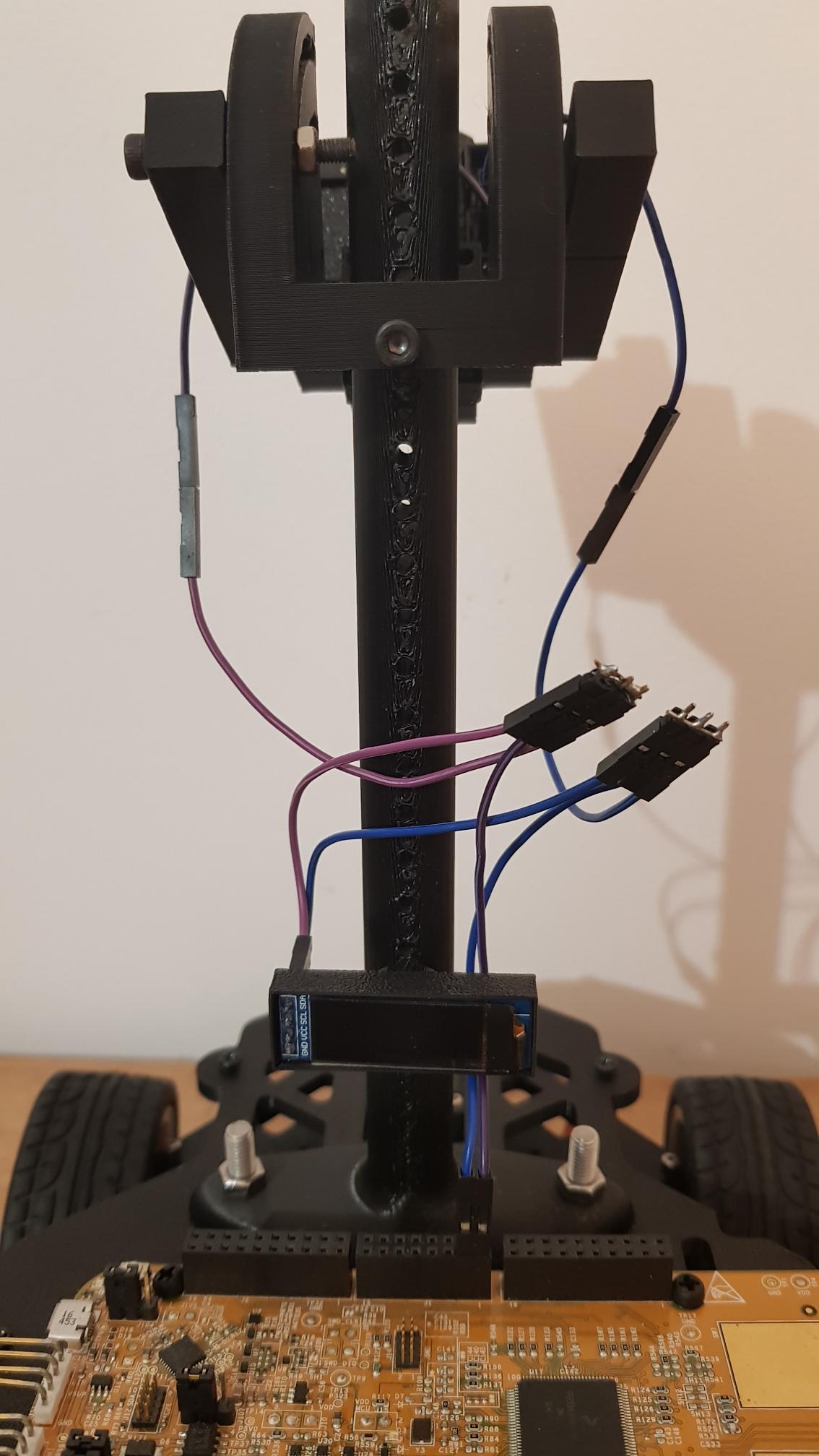
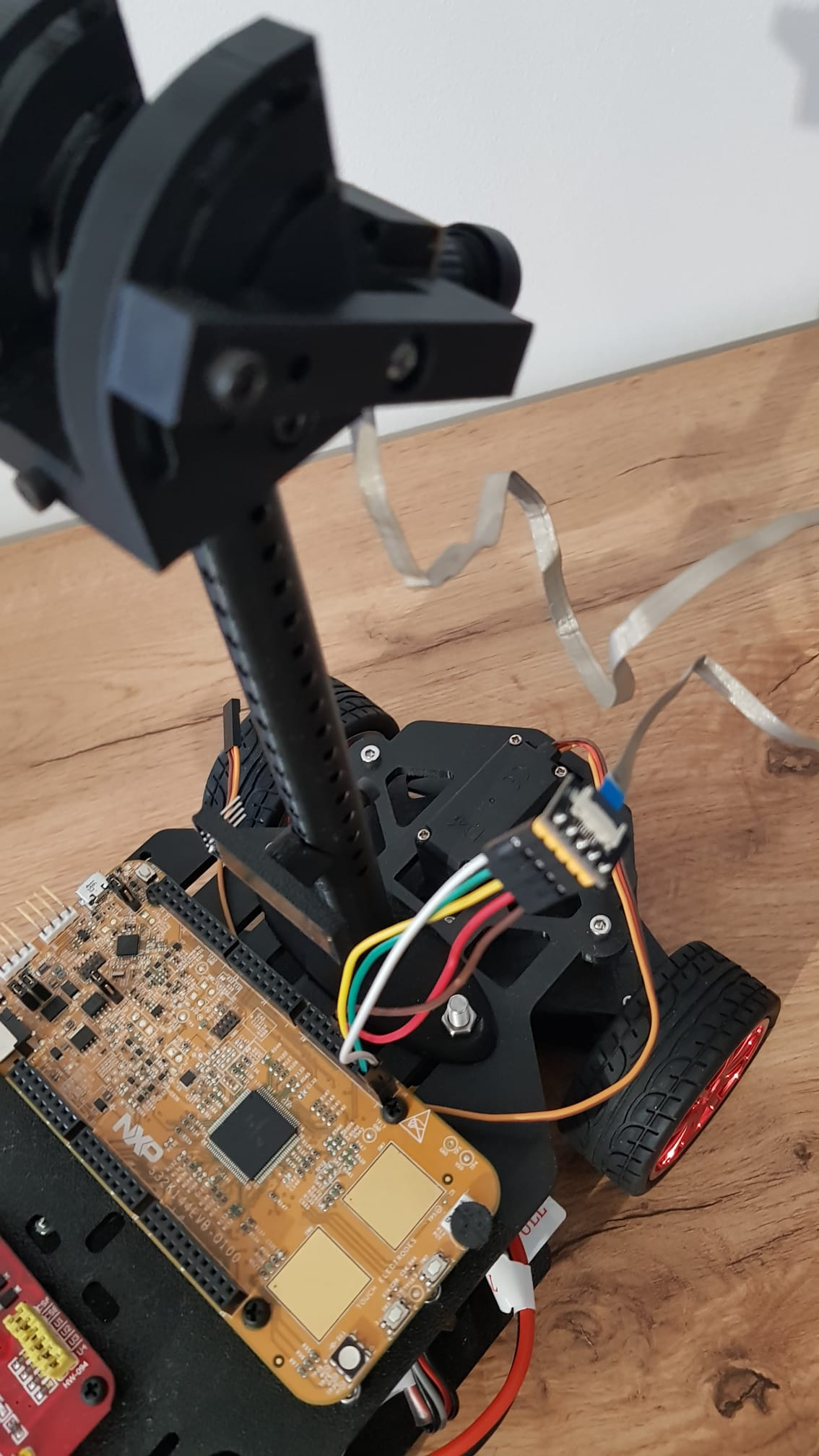
All connections

Ribbon cable breakout board connections
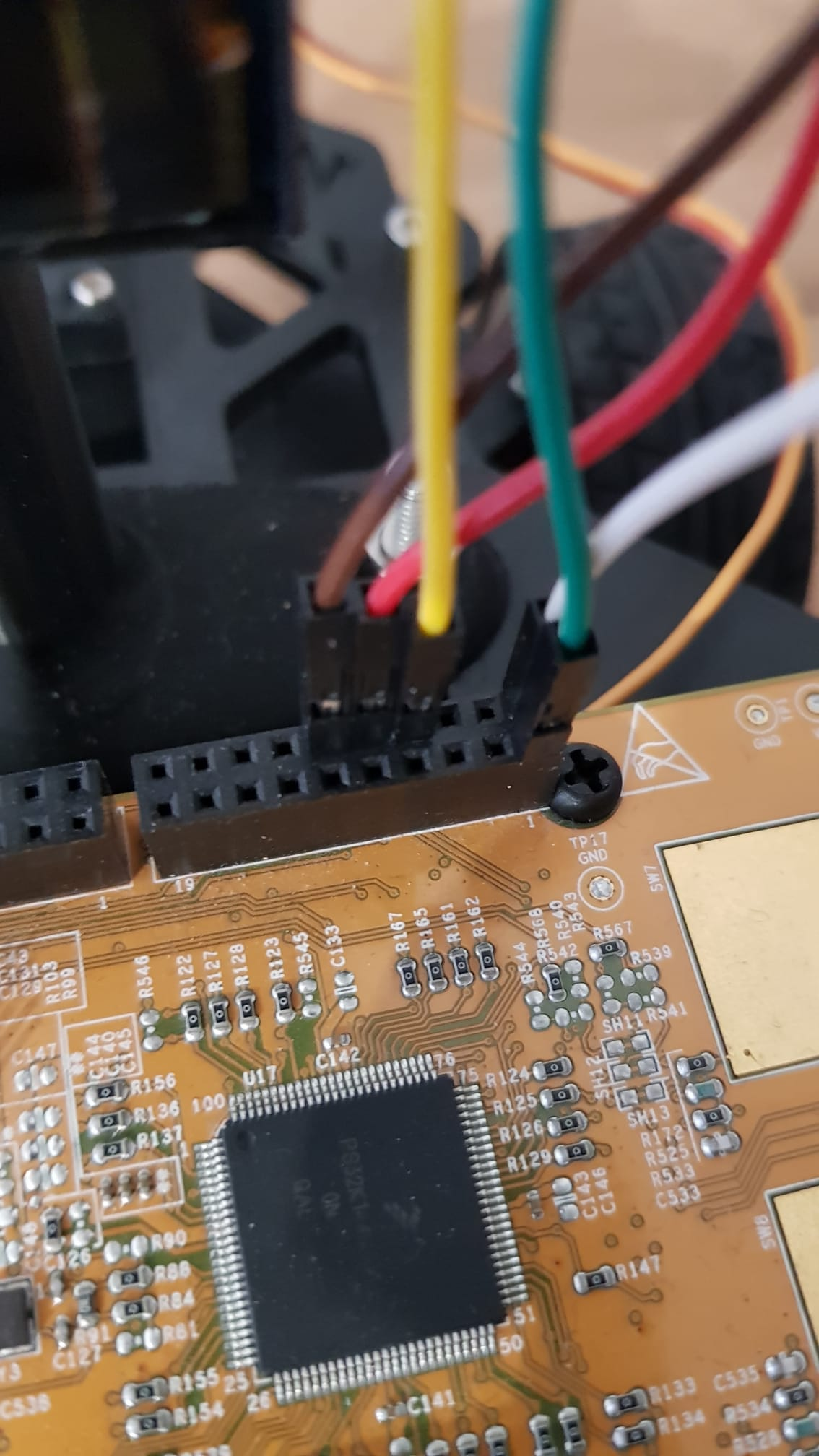
Board connections
.jpg?alt=media&token=808b277b-432e-4533-8a75-ea76f5a41108)
.jpg?alt=media&token=a25ef7b0-de97-4dcb-9e32-2d52d4566710)
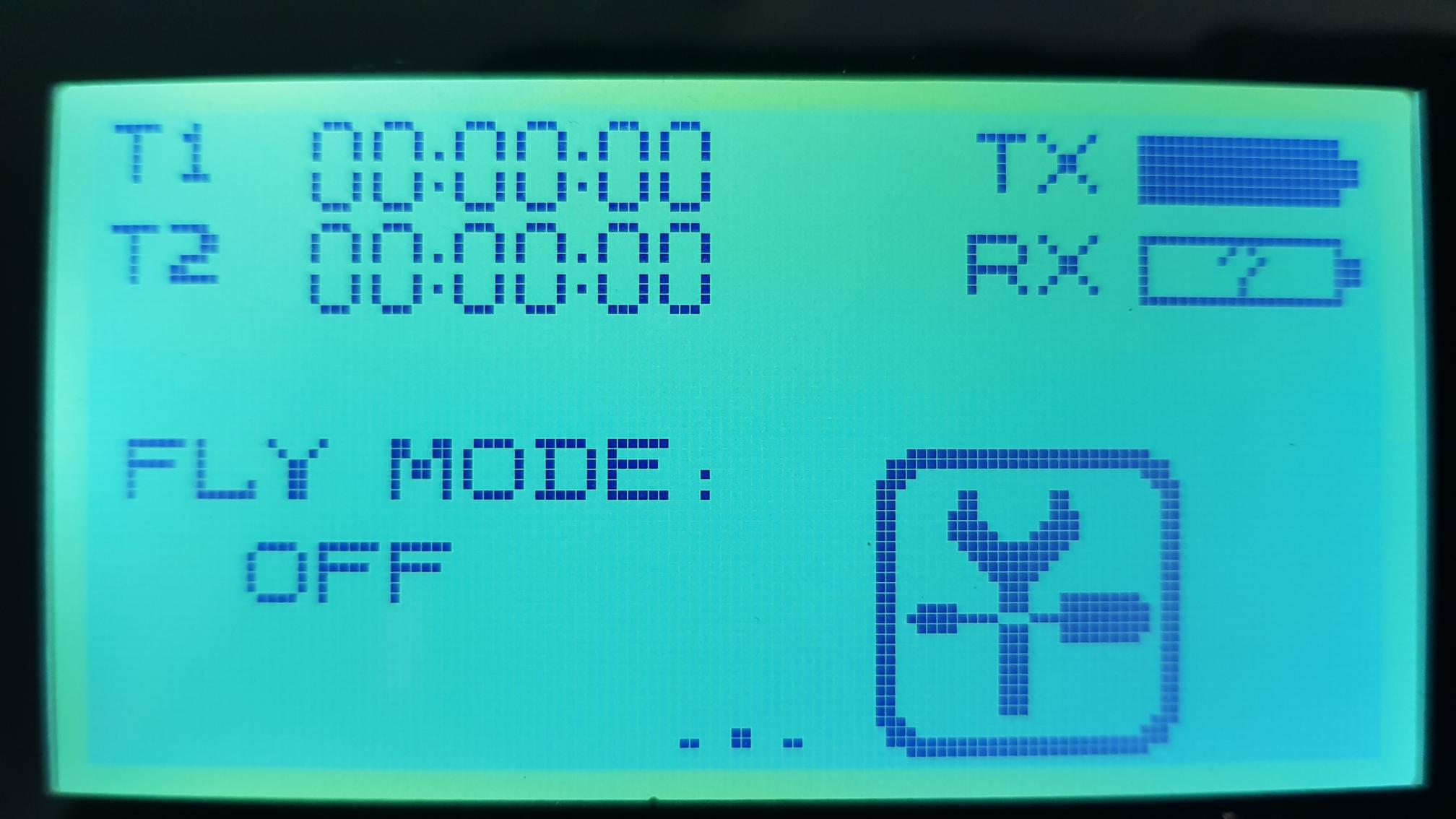
Initial remote screen
Screen after holding the 'Lock' button
.jpg?alt=media&token=c9f0d7c3-ee6a-4abe-b9ed-57cb0fd30499)
New 'Function' menu
.jpg?alt=media&token=fc0acb63-3ef1-4cc7-9946-b1b97fc8a969)
'System' or SYS menu
.jpg?alt=media&token=99e0a3c3-4aa0-4372-bf71-1f4b4f3118bf)
Scrolled down in the 'System' tab to find 'Output'
.jpg?alt=media&token=e3a2c8cc-661a-4110-acbf-bf3c7212c6e2)
Output mode configured to use PPM