Please refer to the NXP.com landing page https://www.nxp.com/navqplus for NavQPlus for availability, pricing, availability and distribution channels.
At times inventory may be held for special events such HoverGames, therefore do not assume that on NXP.com, "pending inventory" means it is out of stock when participating in one of these events.
NavQPlus Part numbers
PLEASE NOTE: There are currently TWO variants of the NavQPlus available the part numbers start with 8MPNAVQ:
8MPNAVQ-8GB-XG This variant does not include the IX Industrial gigabit ethernet Connector and PHY on board. All other components are installed including 100BaseT1 and WiFi. Ethernet over USB-C "gadget mode" is also available.
8MPNAVQ-8GB-G This variant includes the IX industrial connector and Gigabit Ethernet PHY
Presently the following third party companies are able to provide commercial support for NavQPlus, including software support, prototyping derivatives, and/or volume manufacturing of the SoM or carrier board. Please contact the NXP Mobile Robotics team if you have a variant that you would like to let people know about:
Third party manufacturers
NavQPlus is an open design, and source schematics, board Gerber and BOM files are available for download from NXP. You are welcome to refer to, modify, and build these on your own at any contract manufacturer of your choosing.
A small form factor companion computer for mobile robotics applications, featuring the i.MX 8M Plus application processor, able to run Ubuntu Linux.
Also take a look at some of our other GitBooks:
: Quick reference and index for all our mobile robotics solutions.
Introduction
The 8MPNAVQ or "NavQPlus" is a small purpose-built Linux computer evaluation kit (EVK) based on the NXP i.MX 8M Plus SoC. It is focused on the common needs of mobile robotics systems, with a small form factor, Dronecode-compliant JST-GH connectors, and available software stack including Ubuntu Linux and ROS2.
The entire design is available for companies building their own similar hardware. NavQPlus is built as a stack of boards, the top board being a SoM (System-on-Module) containing the processor, memory and other components with strict layout requirements, and where the secondary boards are relatively inexpensive (often 4 layer boards) and allows for versions with customization to be easily built.
Note that the SoM is almost identical to the larger NXP EVK for i.MX8M Plus with the exception of the I/O voltage level being changed to 3.3V. This makes NavQPlus an excellent stepping stone or bridge from the large EVK to a system that can be duplicated for testing in situ, or even copied directly for your application.
NXP i.MX 8M Plus SoC on a SoM with LPDDR4 DRAM and eMMC flash.
4x Arm Cortex-A53 core
1x Arm Cortex-M7 core
The NavQPlus is suitable for many purposes, including generic robots, various vision systems, and AI/ML applications.
Unmanned Aerial Vehicles (UAVs)
Such as multicopters and VTOL (Vertical Take-off and Landing) aircraft
Rovers and other unmanned ground vehicles (UGVs)
Two specific complete developer tool examples are the , and the .
The intent of the 8MPNavQ in HoverGames is to enable participants with a solution that allows them to harness common robotics packages and libraries such as:
ROS/ROS2
OpenCV
GStreamer
The 8MPNavQ runs Linux with a package manager, so you should be able to install the packages that you need to complete your projects successfully and efficiently.
1x Neural Processing Unit (2.3 TOPS)
1080p60 H.265/H.264 encoder
Dual Camera Image Signal Processor (HDR, Dewarp)
A secondary board with connectors to hardware interfaces, such as:
Dual MIPI-CSI camera interfaces
Two CAN-FD interfaces
I2C, SPI, UART, GPIO
SD card slot
2.4/5GHz WiFi and Bluetooth 5.0 using -based
Micro-HDMI, MIPI-DSI, and LVDS for displays
USB-C, including power input & output
1 Gigabit Ethernet with ix Industrial connector
JTAG BOOT
Road-going Delivery Vehicles
Robotic Lawn Mowers
Robotic Vacuum Cleaners
Marine Vessels
Camera and Vision Processing Modules
Time-of-Flight (ToF) Cameras
AI/ML Inference
Cellular Gateway
Vision systems in other applications
e.g. a hospital bed monitor that detects if a patient is sitting up or at risk of falling out of bed.
pyeIQ
TensorFlow/TFLite
PyTorch
Arm NN
etc.
And more!
: NXP Buggy3 Rev B platform using NavQPlus and MR-CANHUBK344
: Drone & rover dev. kits, with FMUK66 vehicle management unit.
: Autonomous model car competition for students.
: Small form factor CAN-FD to 100BASE-T1 ethernet bridge.
We are making a continuous effort to improve this GitBook, some pages and sections may still be a work in progress. Your input and feedback is very welcome. You may provide feedback in our Discord channel (to access the channel you must first join the Hackster.io Discord server). Alternatively, you can open an issue or pull request to the GitHub repository that mirrors this GitBook.
This chapter will cover the basics of connecting to the NavQPlus.
For a quick setup guide follow the instruction on the previous chapter.
For more detailed information follow the hardware reference section.
Quick start guide
Step-by-step instructions on how to quickly set up your NavQPlus
Following these 8 steps, you will be able to start using the NavQPlus in no time. When needed, more information is available in the detailed instructions chapter. Also checkout the TurtleBot4 / iRobot Create3 documentation, and the other parts of this GitBook.
1. Download an Ubuntu image
Download the latest Ubuntu image for NavQPlus (in .wic file format) from GitHub:
For use with iRobot Create3 (AKA Turtlebot4)
For use with NXP MR-B3RB
uuu is an NXP command line tool that runs on a PC and can commnicate directly with the MPU on the NavQPlus. To flash the eMMC memory on your NavQPlus (next step), you will also need to download the uuu tool ("Universal Update Utility").
Download the latest release from GitHub:
Make sure to download the correct application for your platform. The .exe file is a Windows executable. The file named "uuu" without extension is a x86/64 Linux binary.
Before plugging in the board, find the on your NavQPlus and flip them to the "flash" mode. See the table and picture below for reference.
Mode
Switch 1
Switch 2
The NavQPlus firmware is preferably installed on eMMC memory for reliability reasons, even though it may be convenient during development to use the SD card. Especially if you are flying a drone, vibrations may cause (occassional) failure of the physical connections to an SD card.
Connect the NavQPlus to your computer using the leftmost USB-C port (USB 1). The two status LEDs should light up as shown above.
Open a command line window. Run the following command to check that the NavQPlus is recognized by UUU:
You should see that there is a device detected. To flash your board, use the command below (adapt the filename/version to match the image file that you downloaded in step 1):
Once this process has finished, make sure that the flash process was successful by comparing the program output to the image below.
You should now (again) change the to boot from eMMC (also see step 3).
Mode
Switch 1
Switch 2
Power on the NavQPlus by plugging in a USB-C cable to the centermost USB-C port (USB2). Make sure to provide enough power (a >5W supply is recommended). The NavQPlus will boot, and you will be able to confirm it has fully booted by observing the LEDs on board. The three LEDs by the USB1 port should all be on, as well as two LEDs next to the CAN bus connectors.
To log into NavQPlus for the first time, you can either use the included USB to UART adapter, ethernet, or USB gadget mode.
Connect the included USB to UART adapter to the UART2 port on the NavQPlus, and open your favorite serial console application (e.g. PuTTy for Windows users, Minicom on Linux). Open a serial console and set the baud rate to 115200. If there is no output on the screen, try to press enter to get a log-in prompt.
If the boot was successful, in the terminal it will ask for the username and then the password. The default username/password is as follows:
At this point you can start playing around already with the NavQPlus. However, it is recommended to also follow the last steps.
To connect to the board over ethernet, connect the included ix Industrial ethernet cable to NavQPlus, and connect the RJ45 connector to your computer, switch, or router on your local network. You can log into NavQPlus over SSH. More information on this setup is explained in the . The default hostname for NavQPlus is imx8mpnavq or use the IP adress from your board instead. To SSH into NavQPlus, you can run the following command:
It will also ask the password after a successful connection to your board. As mentioned above the default password is user.
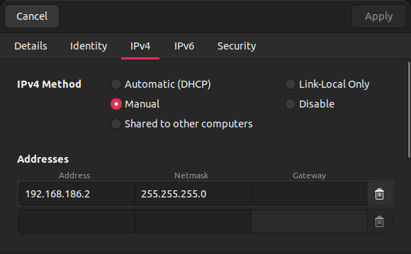
The IP address of the usb0 network interface on NavQPlus is statically assigned to 192.168.186.3. If you want to use USB gadget ethernet to connect to NavQPlus, you will need to assign a static IP to your existing gadget ethernet interface on your computer.
First go to your network settings and click on the plus icon on the top right.
The network configuration is as follows:
IP Address: 192.168.186.2
Network Mask: 255.255.255.0
Once you have set up your USB-C gadget ethernet interface on your computer, you can SSH by running:
The flashed images MAY need expanding to utilize all the available storage. After logging into the NavQPlus, open a terminal and run:
Expand image on the eMMC memory (if you followed the instructions above):
Expand image on the SD card (if you chose to flash the image on the SD card):
To change the default username and password, use the commands below.
Username (replace <new_username> with your desired username):
Password (you will be prompted to enter the current and new password):
Now with the NavQPlus setup complete, you can start to install other software packages and run your own code. For example, (Robot Operating System) is commonly used as a framework for controlling robotic systems, with plenty of compatible packages being available.
There are two ways to power the NavQPlus. You can power it through the PWR IN port or through the middle* USB-C port (*dependent on software image loaded)
This is because it is possible that the USB-C power management logic may be configured in software in a manner that limits current or resets the power management in the time between the bootloader running and the Linux image running . This leads to unexpected behavior at power up. If you suspect something unusual is occurring on power up or you see the board rebooting, please try powering through PWR_IN first.
The PWR IN port accepts an input in the 5V-20V* range. (Technically higher (24V?), but has not been fully validated or characterized)
The PWR IN port pinout schematic is as follows: (center pin is unused). Pin 1, 2 are the power input, Pin 4, 5 are negative (GND).
The input power voltage connection PWR_UNREG is 5V-20V
If you encounter unexpected resets, it could be any of the following issues
That your power supply is not able to provide enough current for the board or the board + peripherals resulting in a brownout condition when internal blocks, interfaces, peripherals turn on and draws additional current.
Supplying power with a LiPo battery may help debug if you have a bench or wall adapter power supply limitation.
The PWR IN port is connected to an onboard power control switch that can sense reverse current spikes on the power supply and de-assert a power good signal, causing a reset. This may happen when another device is sharing the power supply and "glitches" the power supply when plugged in live. A reverse blocking diode and additional bulk capacitors on a power distribution board or inline with the power cable may be desired.
As mentioned above, when powering from USB-C, the specific Linux image should be checked to ensure that the Linux Kernel is not resetting the USB power when it starts up after the bootloader is completed. (i.e the bootloader configures USB-C, then the Linux Kernel may also be set to re-configure/reset the USB-C also and in the process switching it off again.
NEVER use USB-C to USB-A cables without a hub or blocking device. In this embedded platform software has complete control over USB-PD and it is POSSIBLE to provide power >5V on the USB-C connector without handshaking. USB-A is only 5V tolerant and this can damage certain devices.
It is preferred to power the board through the PWR IN port for highest reliability.
Unexpected Power Resets
Insufficient Current Available:
Power Glitch from other boards:
Linux Image problems:
Application Software
The NavQPlus may be considered a generic embedded Linux Computer. When running Ubuntu POC, most linux packages may be installed using apt or apt-get. As with any Linux machine not all packages are suited to the specific hardware.
There is also specific emablement related to the i.MX 8M Plus SOC chip that is used. Please refer to NXP.com for more details. This includes things like hardware acclerated video using gstreamer and hardware accelerated neural net processing using eIQ on the NPU module.
Note that the will demonstrate the usage of NavQPlus as a Robotic platform running ROS and is considered one of our reference development tools. Following the software guides there may be preferable, and provide more detail.
This image uses Netplan to configure the network manager which is "Networkmanager".
Setting the IP address using ifconfig will NOT be applied persistently, and can/will be overridden periodically by Networkmanager
This manages network conflicts for controlling IP networks like Ethernet and WiFi.
Network Manger has several command line utilities
nmcli to get current network status
nmui is a termnial user interface to modify connections
set static IP/ DHCP
set DNS
connect to a wifi network
Examples are provided in the and sections.
You can follow this tutorial below in order to set Static IP with NavQ+ :
For more information please refer to online documentation regarding Netplan/Network manager.
You may wish or need to modify your NavQPlus to accept additional camera types. This is not difficult, but does require care.
EARLY pre-production version of the NavQPlus shipped with a Google Coral autofocus Camera based on OV5645 image sensor. If you have an innowave OV5645 camera this procedure has already been done on your board.
The Production "RevB version" of the NavQPlus makes a small adjustment to the MIPI CSI Clock line in order to be more compatible with a variety of image sensors. This is also the configuration used with the OV5645 fixed focus image sensors from Innowave that ship with the RevB board
As shown in the image below, the resistors R21 and R37 shoudl be 0 Ohm (or solder jumpers) and the resistors R22 and R38 should be removed. (DNP/DNI).
UARTS
Multiple UARTs are available on NavPlus
There are multiple UARTS on NavQPlus.
Because of pinmuxing these can sometimes be assigned to different uses and locations depending on the specifics of the Linux BSP and DTB files. The default configuration for NavQPlus LInux image provided at time of publication will be described here. Please double check any notes on your specific Linux Image if something varies from this configuration.
External UARTs on NavQPlus
I2C
Accessing the external I2C bus
The i.mx 8M Plus has a number of I2C busses on board. Internally they are connected to a variety of onboard peripherals. Normally you will not need to address these peripherals directly, and they will be handled by Linux drivers.
I2C1 - SOM only for PMIC control
I2C2 - MIPI CSI1, LVDS1, DSI
I2C3 - MIPI CS2, LVDS2, PCIe
I2C4 - USB1 TCPC, USB2 TCPC, Secure Element, RTC
TCPC1 I2C ADDR: 1010001X
TCPC2 I2C ADDR: 1010010X
AUX connector: I2C bus #6 is pin-muxed with UART4 to the six pin JST-GH J12 connector and is the external I2C bus is enabled on the AUX port of the NavQ+.
By default these are configured for I2C and not UART4 (internal MCU)
A table of the J12 pinout is below. Note that pin 1 is on the left side of the connector:
Pin
Function
Voltage
You only need to use pins 1, 2, 3, and 6 for I2C.
These GPIO are 3.3 volt tolerant only.
To detect that a device is present on the bus, you can run the following command:
You may need to add the 'user' user to the i2c group to access the bus. To do this, run the following command, then log out and log back in:
The SE050 or SE05x secure element will not respond to an i2cdetect command. "Plug and Trust" software library should be used to interface with the external Secure Element.
RTC I2C ADDR: 1010011X
PD1 I2C ADDR: 1110010X
PD2 I2C ADDR: 1110011X
SE050 I2C ADDR: 1001000X
3
I2C_SCL
3V3
4
GPT1_CAPTURE1
3V3
5
GPT1_CAPTURE2
3V3
6
GND
GND
1
5V
5V
2
I2C_SDA
External I2C #6 on AUX Connector
Note that UART4 typically is used to connect to the internal Microcontroller of the i.MX 8M Plus, and it is also pinmuxed on J11. The two alternative pinmuxing locations are so a custom Linux DTB could be configured depending on your needs for UART4, SPI2 or I2C.
I2C device detection
Secure Element and i2ddetect
I2C (I2C6) Locator
Schematic
The I2C port is multiplexed with UART4 on the NavQPlus. This is configured in the Linux DTB files. Therefore the schematic below shows the UART signal names. The Multiplexed I2C signal names are shown on the far left of the image
Location of I2C #6 on AUX connector
3V3
i2cdetect -y 5
sudo usermod -a -G i2c user
UART3 (SPI)
UART3 for users
Introduction
UART3 is available for general use. Hardware flow control is supported.
Note from the schematic clip below, that the MPU can multiplex these signals with SPI1. This is normally configured in the Linux image and is not the default configuration.
UART3 Interface voltage
The signaling from the SOM to the NavQPlus carrier board on J9 is at 3V3 but the Murata 1ZM expects 1.8V. The level conversion is done using U26.
UART3 Locator
UART3
Schematic
UART3/ SPI 1 interface on J9
All the UART signals are protected from ESD using the Nexperia IP4292CZ components. This is part of an optimized BOM as they are also required for the USB interfaces. In additional to its exceptional performance the board layout may be optimized because of being able to route traces straight under the component.
UART3 may be accessed as a standard /dev/ttyS_ in Linux.
UART3 may be accessed /dav/ttymxc2 in linux
<TODO-check wich ttyS number it is>
MIPI CSI (Camera)
Connecting the Innowave OV5645 Camera
<todo> add more detail
The innowave camera comes pre-installed with the latest revision (2024) of the NavQPlus. It is a fixed focus camera unlike the autofocus google coral camera. The installation and removal is very similar to the the instructions below for the Google coral camera.
The flex cable has marking on it "this side up" that should be visible when looking at the connector side of the board. i.e you can read "this side up" and also read the silkscreen "CSI 1"on the bottom of the board at the same time.
Connecting the Google Coral Camera
CAUTION! If the Google Coral Camera is connected backwards, it will cause a short circuit and burn out both the MIPI-CSI cable and the sensor in the camera. Please see the images below on how to properly connect the Google Coral Camera to the NavQPlus.
One Google Coral camera is included with most NavQPlus kits. The NavQPlus does support two MIPI-CSI Cameras simultaneously. Additional Google Coral cameras and extended ribbon cables are available from Google, or other retailers.
Pin 1 (P1) on the Google Coral Camera should be connected to the pin with the arrow on the MIPI-CSI port. Please see the images below. The sides with the red box should line up. You should see the blue on the flex cable when connecting to the MIPI-CSI port.
Red box shows pin 1 on the camera.
Red box shows pin 1 on the MIPI-CSI connector.
Image reference of how the camera should be connected to the NavQPlus. Please note the orientation of the flex cable. This is very important!
Image shows the Google Coral Camera connected to the NavQ+.
Camera Mount
Depending on your kit, there may be a tall or short camera mount included. The short version typically ships with the NavQPlus or drone itself, while a tall version may come with an MR-Buggy3 development kit. Please refer to the image below for information on how to assemble.
The camera mount is provided unassembled.
Software
ESD Protection components on UARTS
See drawing PDF below. Note the three three screws (item 10) and nuts (item 8) that connect the inner case (item3) to the camera adapter (item 2). This is a little difficult to see on the drawings.
FYI the camera mount base is designed to be compatible with other off the shelf "action cameras" and uses a #10-32 screw to attach. Other designs, accessories or modifications can easily be 3d printed and adapted.
PCIe signals are on a flex cable connection located on the back of NavQPlus. A PCIe adapter has been prepared by a 3rd party to work with NavQPlus. It is not in production as of yet. Please contact hovergames@nxp.com for more details.
GPIO
There are several ports which may have or may be configured for GPIO connection. In addition there are several SMT pads designed to allow access to GPIO and signals such as the PMIC controls. Refer to the schematics for details.
<<TODO - add more detail here, and pictures of the schematics. Add an example pin access if available>>
UART4 interface voltage
The signaling from the SOM to the NavQPlus carrier board on J11 is at 3V3
Alternative output is on the AUX connector at location J12 also at 3V3 signalling. However this is not the default linux BSP, and would require changes to the dtb files.
Schematic
Note that J11/UART4 is the default location for UART4 signals. Also by default UART4 is assigned to the M7 Core on the i.MX8M Plus. An RTOS such as FreeRTOS or Zephyr would normally use it as the default console to the embedded MCU.
You may note that the signal names are differed on J11 vs J12. This is only a labelling detail, since the pinmuxing on the chip is used to "move" the UART4 interface from one set of pins on the MPU (and board to board header). In order to route these signals independently on the carrier board, they need their own net names.
All the UART signals are protected from ESD using the Nexperia IP4292CZ components. This is part of an optimized BOM as they are also required for the USB interfaces. In additional to its exceptional performance the board layout may be optimized because of being able to route traces straight under the component.
Remote control setup
Use the FlySky FS-i6S RC transmitter with NavQPlus
Introduction
An RC remote control can be made to connect directly to the NavQPlus in order to transmit joystick and switch settings information. This can be then used in other software (ROS2) as input to control aspects of a vehicle directly or indirectly, such as reading an RC channel as an "arming switch". Note that this method uses a USB-UART adapter to facilitate the connection, but technically it is possible to create a direct serial connection.
There may be more than one way to attach an RC remote to the NavQPlus and in general to a robotics vehicle. Reminder that It may be preferable to attach an RC remote to an MCU board acting as a real time controller, such as MR-CANHUBK344 or MR-VMU-RT1776, at a lower level and have communication from that board go "up" to the NavQPlus
Requirements:
FlySky FS-i6S RC transmitter
FS-i6B receiver
NavQPlus baseboard with Ubuntu image release 22.04.3 or above
FTDI type USB-UART cable/adapter
Connect the FS-i6B receiver to NavQPlus using TTL-UART cable (you need to prepare this cable yourself).
Connect the cable to a general use UART connector (the board is equipped with 4 connectors, three of them are available for general use. (Note UART1 is assigned internally to communicate with the Bluetooth portion of the WiFi/BT Wireless module on the NavQPlus Baseboard). Check this for more details.
Connect the three TTL wires Black/Red/White to the FS-i6B receiver as depicted in the picture below:
After plugging the receiver to NavQPlus board, you should see a red LED blinking in the receiver. If your transmitter is already on, it should bind automatically to the receiver otherwise you can bind it manually under its system menu. After binding, the red LED should be constantly glowing.
Under NavQPlus linux console, run the following command in the background in order to create a new joystick input device:
Now your receiver is attached, you can use it for your need (ROS, software simulation, ...)
In order to check it is detected properly, run jstest-gtk software.
The new controller should show up as "FS-iA6B iBus RC receiver". The bar graphs should change accordingly when you move the control sticks.
sudo inputattach --fsia6b /dev/ttymxc2 &
For more information about configuring the FlySky FS-i6S transmitter, please refer to this .
Wiring
RC Binding is simply the process to assign an RC Receiver to the RC transmitter. It is covered in the FlySky documentation. Generally you put the TX in "bind mode" and then power up the RX with a jumer across the bind pins.
Software setup
The fsia6b driver is integrated since the Ubuntu , so you need at least this version in order to run the setup.
A Micro-HDMI interface is provided on the NavQPlus. This may be used to drive typical monitors or small LCD displays. Note only typical display timing and resolution is enabled/supported by default.
A standard micro-HDMI cable may be used to connect to a typical monitor, or HDMI embedded displays.
Extra - HowTo Linux notes
Notes and tips
This page is a seried of helpful notes that have been gathered as a result of HoverGames and other feedback from users with NavQPlus.
HowTo: Remove unattended upgrades
<TODO> Add a simple explanation on why to remove unattended upgrades
apt remove unattended-upgrades
HowTo: Install nano
GNU nano is an easy to use command line text editor for Unix and Linux operating systems. It includes all the basic functionality you’d expect from a regular text editor, like syntax highlighting, multiple buffers, search and replace with regular expression support, spellchecking, UTF-8 encoding, and more.
Note: There are other text editors that can be used, Nano is a popular one. Some of the HowTo below will use Nano as the editor.
To install:
sudo apt install nano
HowTo: Edit hostname
Run the following command to change your hostname. Assuming you want to use the hostname "compcom42".
nmcli con mod "Wired connection 2"
  ipv4.addresses "192.168.42.11/24"
  ipv4.gateway "IP_GATEWAY" (needs to be blank on static ip)
  ipv4.dns "1.1.1.1,8.8.8.8"
  ipv4.method "manual"
3D Printer Files
We welcome user submitted 3d printer files for use with NavQPlus and NXPHoverGames, NXPRoverGames, NXP-CUP or other. Note you may also find 3D printer files in other NXP Gitbooks, and by searching Thingiverse or other 3d printer file repositories with some of the name above.
In addtion on the following pages there are also direct links to Fusion360 files used with NavQPlus, HoverGames drone, and MR-Buggy3
YouTube Links
Links to 3rd party helpful youtube videos.
Misc YouTube links that may be relevant to NavQPlus.
<TODO> Check links
MAYBE LINKS:
Simulating Robots with Gazebo and ROS | Getting Ready to Build Robots with ROS
Here are some tips an tricks related to the desktop/laptop linux host computer that you may use to connect to your NavQPlus.
Note that these tips and notes are NOT generic, and usually related to very specific releases or configurations. ensure you understand the notes and that they apply to your particular configuration.
Ubuntu HOST laptop cannot screens share in MS Teams
Reported June 2023 - IAFG
We often communicate, and have debug sessions using Microsoft Teams, (or Zoom). During a session on Teams it is helpful to share the screen of the Ubuntu Host.
Current Ubuntu distributions (22.04) may only enable Wayland graphics by default. However X is required in order for screensharing to work with TEAMs and ZOOM (possibly others).
Depending on your LInux distribution you may be able to switch to X simply by logging out. Use the small gear icon in the lower right of the screen to then select Ubuntu using X.
Below is a copy of the instructions given in the link:
To disable Wayland and use xorg only:
Open your terminal and write sudoedit /etc/gdm3/custom.conf
Uncomment the value waylandEnabled=false -- just remove the #
Press Ctrl+O then Enter then Ctrl+X
Reboot your computer.
MicroDDS Agent/MicroROS
Introduction
The following was user contributed content and edited by NXP. Note that there are several methods available for communication between ROS and PX4. This documents an established method.
Setting up the MicroDDS Agent/MicroROS
One method used to communicate between the NavQPlus and the FMUK66v3 using T1 or Serial is by using MicroROS or the XRCE-dds Agent.
To install these tools:
git clone https://github.com/eProsima/Micro-XRCE-DDS-Agent
cd Micro-XRCE-DDS-Agent
mkdir build && cd build
cmake ..
make
sudo make install
If using yocto, you can use the WIP meta package in your recipe.
https://github.com/dirksavage88/meta-dds
Alternatively, you can install micro-ROS through the ubuntu snap store
Another way to get micro-ROS is through Github as a ROS2 package. You can use the colcon build tools after sourcing the ROS setup.bash script in "/opt/ros/galactic/setup.bash"
colcon build --symlink-install
Follow the instructions for each package on how to run the agent. The agent is a broker for clients on the network (including the FMUK66) and allows topics from the pixhawk to be shared with the DDS global space.
To set up the NavQ+, follow instructions in the Setup Guide -eMMC for a static IP. The FMUK66 is IP "10.0.0.1". As an example, you can set the NavQ+ to "10.0.0.3" with a blank ipv4.gateway (no quotes or anything) on Wired Connection 1.
Then start the microdds agent that is installed in the home directory in the Micro-XRCE-DDS-Agent build folder.
On the FMUK66, ensure you have flashed to main and enter the following command.
You should see the topic listed in the mavlink console after running the client start, as well as topic, publishers, data writers, and creators on the agent side.
./MicroXRCEAgent udp4 -p 2019
microdds_client start -t udp -h 10.0.0.3 -p 2019
ROS2
If using an downloaded image, check first that these packages are not already installed.
See MR-B3RB for an already pre-configures ROS2 installation. This is the preferred method.
Installing ROS2 on the NavQPlus
We have prepared an install script that will install ROS2 and all necessary packages on the NavQPlus.
To get the install script and run it, you can run the following in the terminal:
If using an downloaded image, check first that these packages are not already installed.
Inference examples
The i.MX 8M Plus SOC in the NavQPlus contains a Neural Processing Unit (NPU) that can accelerate inference on the edge. There are some inference examples built into the NavQPlus image that will do image classification with the COCO dataset.
There is a TensorFlow Lite example in the /usr/bin/tensorflow-lite-2.6.0/examples/ folder. This example runs a mobilenet_v1 quantized image classification model. To run it, try the command below:
USE_GPU_INFERENCE=0 specifies that we want to run inference on the NPU. Removing this environment variable will run inference on the GPU.
To run inference on the GPU/NPU, you will need to use the libVX delegate, at the path /lib/libvx_delegate.so.
There is also a python script named label_image.py that contains example code for inference with TFLite.
ROS2 example
A simple ROS2 example
Introduction
This page will go through a simple example using ROS on the NavQPlus. More examples and details can be found on the ROS webpage linked bellow. This example is a shortened version of the Publisher Subscriber for Python tutorial. You will need to have ROS2 installed already before trying this example.
ROS2 Publisher Subscriber in Python example
In this tutorial, you will create nodes that pass information in the form of string messages to each other over a topic. The example used here is a simple “talker” and “listener” system; one node publishes data and the other subscribes to the topic so it can receive that data.
Step 1 - Create workspace
First step is to make a workspace for your project to build in. Go to your home folder and create a workspace called /ros2_ws. With another directory inside /src for your project to be in.
mkdir -p ~/ros2_ws/src
Then move into the /src directory:
Now we want to create a package inside the directory we just created.
Your terminal will return a message verifying the creation of your package py_pubsub and all its necessary files and folders.
Navigate to the new directory location created.
Now download the example publisher code:
You should now see a new file located in the py_pubsub directory. To understand more about the code, follow the tutorial through the .
For the subscriber code stay in the same directory and download the following:
With this done you will have both publisher_member_function.py and subscriber_member_function.py files in your directory. Plus, the __init__.py.
The next step is to modify some of the files created to support the code we just downloaded. We will be adding the dependencies. Navigate one level back to ~/ros2_ws/src/pubsub.
Open the package.xml file with a text editor. We will be using nano for this tutorial.
After the <license> line add the following lines of code:
Your new file now should look something similar to this:
Exit the file editor and save.
The next file you will have to modify is the setup.py file.
Add the following line within the console_scripts brackets of the entry_points field:
Don't forget to save!
First, go back to the root of your workspace:
Then, check if you have any missing dependencies in your code by running:
If everything is installed successfully you can build your package with colcon:
With the build finished we need to source the setup files.
Finally, we can run the code. You will need two terminals to run both the publisher and subscriber.
In one terminal run the publisher:
You should see that the code starts running and prints:
On the other terminal run the subscriber:
When you run the listener, you will start to see the message from the publisher:
Use Ctlr + C in each terminal to stop the code.
You created two nodes to publish and subscribe to data over a topic. Before running them, you added their dependencies and entry points to the package configuration files.
Refer to nxp.com/navqplus order page for the exact details on what is included in the NavQPlus version that you have ordered.
The exact contents is based on the version kit ordered, Typically the following items are included:
8M Plus SOM + Baseboard, flat heatsink, 3d printed enclosure
Wifi Antenna attached
Communications cables
FTDI USB-UART Serial console cable and adapter board/Cable
IX-industrial to RJ45 Ethernet cable (not on -XG version)
2-Pin JST-GH Cable for two wire 100BaseT1 automotive ethernet
Power Cables
5-Pin JST-GH power cale to RED SYP type cable
RED SYP type cable to XT-60 battery connector
Camera
Omnivision OV5645 on innowave module. (typical)
Several cameras are available to connect to the MIPI CSI interface.
Caution and Disclaimers
Refer to the HoverGames disclaimer below when using NavQPlus with a drone or similar vehicle.
It is expected as a user of NavQPlus, you will have basic knowledge of how to operate an embedded Linux computer in a headless terminal environment. While NavQPlus can support a desktop environment, it is not a "PC" or desktop computer, and therefore many graphical applications designed for these devices will not work due to device specific libraries and graphics drivers.
If you are not comfortable operating a Linux computer in a terminal environment, below are links to some resources that may help.
NavQPlus_MR-Buggy3 Tradeshow Demo Guide (2022)
The NavQPlus_MR-Buggy3 demo is a demonstration of the capabilities of the NavQPlus, the MR-Buggy3 platform, and NXP's CAN Bus hardware and software support for ROS2.
This guide will walk you through setting up the MR-Buggy3 demo on both your laptop and the NavQPlus. This demo consists of:
A Gazebo Ignition simulation environment with the MR-Buggy3 model running
Connection to the actual Buggy3 hardware meaning HITL (hardware in the loop) control of the real life MR-Buggy3
2x 4-Pin JST-GH with center wires twisted for CAN cables.
USBC to USB A cable
5-Pin JST-GH power cable to 5-Pin JST-GH power Cable.
A showcase of the NPU (neural accelerator) on the NavQPlus running inference on the real world camera data as well as a virtual camera from the simulation environment
ROS2 <-> Cyphal* <-> uORB transport (*transport layer only)
CAN communications from NavQ+ to the UCANS32K146 CAN-FD node driving a PWM and LED
PWM control in PX4 using the PCA9685
To run this demo, you must have an Ubuntu 20.04 or 22.04 machine. It is recommended that you use a machine that has a dedicated GPU and that is running Ubuntu natively.
This install script first checks itself against the repo to ensure it is the latest version, then installs the packages needed for a baseline setting for the NXP mobile robotics team development environment on either a laptop, VM, or the NavQPlus targets.
Download the nxp_install.sh script using a webbrowser to your local Linux machine.(Currently this) is located at
Run
chmod a+x install.sh
on this script and run it on your machine.
This will install ROS2 and all required dependencies.
It is recommended that you create a ROS2 workspace at ~/git/ros2/, but you are free to create it wherever you want. In this guide, we will use that location. Follow the steps below.
Follow the steps used above for your laptop to set up ROS2 on your NavQ+.
You'll want to also create a ROS2 workspace on your NavQPlus. This step is similar to the step for setting up the laptop, but instead of cloning sim_ignition_bringup, you'll want to clone ros2_orchestrator. Follow the steps below.
Once you have connected everything according to the block diagram shown below, you will be ready to run the demo.
To run the demo, open 4 terminal windows. Start with the battery plugged in and powering everything over the PDB, and make sure that the ESC is turned OFF.
SSH into the NavQ+, then navigate to ~/git/ros2/src/canfd_msgs/scripts/. Inside this folder, run ./launch_example.sh. You should see the UCAN board turn on, start sending heartbeat messages, and then stop. NOTE: You should also see a 64 byte CAN frame get sent. This is the initialization for the PCA9685 PWM Driver. Once this message is sent, you are free to turn on your ESC.
Run ros2 launch sim_ignition_bringup sim_ignition_bringup.launch.py and wait for the simulation to fully start.
SSH into the NavQ+, then run ros2 launch ros2_orchestrator orchestrate.launch.py
This terminal is for checking ros2 topics, launching additional rqt_image_views, and other commands as needed.
You should now have a working demo! The simulated car should be driving around the track. In each of the rqt_image_view windows that open, you can view the various camera streams that are running. Camera streams that are labeled "Debug" show the NPU inference running.
Description
This section documents a tradeshow demo from 2022 using both the NavQPlus and The NXP MR-Buggy3 platform. Please note that this demo is subject to ongoing changes and updates and may at some point be "broken". The information here may be useful for similar types of demonstrators.
On systems where you have upgraded from Ubuntu 20.04 to 22.04 errors may be encountered. This can become somewhat complex to resolve. A clean install is always best. Alternatively, try completely removing the old ROS directories (save any personal work) and any repository references to ROS Foxy vs Humble.
The base thing to try first:
If there is an error with the install.sh script, the first remedy to try is repeating the ROS2 sources install steps as outlined here:
\
Second step: Creating a ROS2 workspace and building sim_ignition_bringup
If you get "CMake Error at CMakeLists.txt:14 (find_package):" then run "source /opt/ros/<distro>/setup.bash"
Setting up the NavQ+
First step: Running the NXP install script
Second step:
If you get "CMake Error at CMakeLists.txt:14 (find_package):" then run "source /opt/ros/<distro>/setup.bash"
General specifications have been requested for NavQPlus. Currently there are no official qualified specifications.
Physical Hardware
The CAD model below and associated measuring tools can be used to determine physical characteristics of interest. The model may also be downloaded in a variety of file formats by following the link to open in Fusion360.
Electrical Specifcations
PLEASE NOTE: These are unofficial specifications only. The values below may be used for guidance, but are not guaranteed.
Voltage input
5-20V
Power supplied via High voltage USB PD power switch(es)
Power input and can be from dedicated connector or through USB-C
A detailed power analysis has not been done. Below are estimates
Expectation is MAX 5W and typical 3W
5W =~12V@450mA
CAD files available for board outline and case though the
90mmx70mm exclusive of case mounting tabs
Tabs 82mm at max width.
98.4grams with Fin type heatsink attached*
* production units use a flat aluminum plate which reduce weight further
FCC CAUTION: Changes or modifications not expressly approved by the party responsible for compliance could void the user’s authority to operate the equipment.
This transmitter must not be co-located or operated in conjunction with any other antenna or transmitter.
Supported Hardware
NavQPlus is a standalone embedded linux device. There are many peripherals that will attach and interface with it, or can be made to interface with the correct drivers.
In addition, the Mobile Robotics team works with several complimentary devices and boards which work with the NavQPlus:
MR-B3RB (Buggy3 RevB): a robotics platform in the form of an ackermann steering small car
iRobot Create3: AKA Turtlebot 4, ROS development platform
RDDRONE-T1ADAPT: Adapter board from 100BaseT1 to RJ45
MR-T1ETH8: T1+RJ45 Ethernet Switch
MR-CANHUBK344: MCU board with S32K344, 6 CAN , T1 Ethernet
CANHUB-ADAP: plug on board with IMU and GPS connectors
MR-VMU-RT1176
Pixhawk V6X standard Vehicle Manangement Unit, with IMU
Note both NuttX and Zephyr Supported on this platform
RDDRONE-BMS772: Battery Management 6S
UCANS32K146: CAN Node board
HDMI displays (Many off the shelf small displays)
Note about the source code provided here in this document
BSD-3 License
Example code shown in this document has the following copyright and BSD-3-Clause license:
Copyright 2023 NXP. Redistribution and use in source and binary forms, with or without modification, are permitted provided that the following conditions are met:
Redistributions of source code must retain the above copyright notice, this list of conditions and the following disclaimer.
Redistributions in binary form must reproduce the above copyright notice, this list of conditions and the following disclaimer in the documentation and/or other materials must be provided with the distribution.
Neither the name of the copyright holder nor the names of its contributors may be used to endorse or promote products derived from this software without specific prior written permission.
THIS SOFTWARE IS PROVIDED BY THE COPYRIGHT HOLDERS AND CONTRIBUTORS "AS IS" AND ANY EXPRESS OR IMPLIED WARRANTIES, INCLUDING, BUT NOT LIMITED TO, THE IMPLIED WARRANTIES OF MERCHANTABILITY AND FITNESS FOR A PARTICULAR PURPOSE ARE DISCLAIMED. IN NO EVENT SHALL THE COPYRIGHT HOLDER OR CONTRIBUTORS BE LIABLE FOR ANY DIRECT, INDIRECT, INCIDENTAL, SPECIAL, EXEMPLARY, OR CONSEQUENTIAL DAMAGES (INCLUDING, BUT NOT LIMITED TO, PROCUREMENT OF SUBSTITUTE GOODS OR SERVICES; LOSS OF USE, DATA, OR PROFITS; OR BUSINESS INTERRUPTION) HOWEVER CAUSED AND ON ANY THEORY OF LIABILITY, WHETHER IN CONTRACT, STRICT LIABILITY, OR TORT (INCLUDING NEGLIGENCE OR OTHERWISE) ARISING IN ANY WAY OUT OF THE USE OF THIS SOFTWARE, EVEN IF ADVISED OF THE POSSIBILITY OF SUCH DAMAGE.
CASE Mounting tabs are 72mmx72mm
CASE / Heatsink secondary mounting 53mmx53mm
IMPORTANT: Software may be constructed which allows power from the dedicated connector to flow to the USB-C connectors without proper and complete driver control over the USB PD device negotiation. IF for example the USB-C connector uses a USB-C to USB-A connector, a higher voltage than is allowed on USB-A may become present. Depending on what USB A device is connected this could cause permanent damage to the USB A device.
This device complies with part 15 of the FCC Rules. Operation is subject to the following two conditions: (1) This device may not cause harmful interference and (2) this device must accept any interference received including interference that may cause undesired operation.
The available scientific evidence does not show that any health problems are associated with using low power wireless devices. There is no proof, however, that these low power wireless devices are absolutely safe. Low power Wireless devices emit low levels of radio frequency energy (RF) in the microwave range while being used. Whereas high levels of RF can produce health effects (by heating tissue), exposure of low-level RF that does not produce heating effects causes no known adverse health effects. Many studies of low-level RF exposures have not found any biological effects. Some studies have suggested that some biological effects might occur, but such findings have not been confirmed by additional research. LBEE5QD1ZM has been tested and found to comply with FCC radiation exposure limits set forth for an uncontrolled environment and meets the FCC radio frequency (RF) Exposure Guidelines.
It is necessary to take a SAR test with your set mounting this module (except to use only Bluetooth).
Class II permissive change application is necessary using the SAR report. Please contact Murata.
This equipment complies with FCC radiation exposure limits set forth for an uncontrolled environment and meets the FCC radio frequency (RF) Exposure Guidelines. This equipment should be installed and operated keeping the radiator at least 20 cm or more away from person’s body.
Contains IC: 772C-LB1ZM
This device complies with Industry Canada’s applicable license-exempt RSSs. Operation is subject to the following two conditions:
This device may not cause interference; and
This device must accept any interference, including interference that may cause undesired operation of the device.
Le présent appareil est conforme aux CNR d’Industrie Canada applicables aux appareils radio exempts de licence. L’exploitation est autorisée aux deux conditions suivantes :
l’appareil ne doit pas produire de brouillage;
l’utilisateur de l’appareil doit accepter tout brouillage radioélectrique subi, même si le brouillage est susceptible d’en compromettre le fonctionnement.
Data transmission is always initiated by software, which is the passed down through the MAC, through the digital and analog baseband, and finally to the RF chip. Several special packets are initiated by the MAC. These are the only ways the digital baseband portion will turn on the RF transmitter, which it then turns off at the end of the packet. Therefore, the transmitter will be on only while one of the aforementioned packets is being transmitted. In other words, this device automatically discontinue transmission in case of either absence of information to transmit or operational failure.
La transmission des données est toujours initiée par le logiciel, puis les données sont transmises par l'intermédiaire du MAC, par la bande de base numérique et analogique et, enfin, à la puce RF. Plusieurs paquets spéciaux sont initiés par le MAC. Ce sont les seuls moyens pour qu'une partie de la bande de base numérique active l'émetteur RF, puis désactive celui-ci à la fin du paquet. En conséquence, l'émetteur reste uniquement activé lors de la transmission d'un des paquets susmentionnés. En d'autres termes, ce dispositif interrompt automatiquement toute transmission en cas d'absence d'information à transmettre ou de défaillance.
This radio transmitter (IC Number: 772C-LB1ZM) identify the device by certification number or model number if Category II) has been approved by Industry Canada to operate with the antenna types listed below with the maximum permissible gain indicated. Antenna types not included in this list, having a gain greater than the maximum gain indicated for that type, are strictly prohibited for use with this device.
: 146153 Dual Dipole antenna Gain: +
: 146187 Dual Dipole antenna Gain: +
: LBEE5QD1ZM-Antenna monopole antenna Gain: +
Le présent émetteur radio (IC Number: 772C-LB1ZM) a été approuvé par Industrie Canada pour fonctionner avec les types d'antenne énumérés ci dessous et ayant un gain admissible maximal. Les types d'antenne non inclus dans cette liste, et dont le gain est supérieur au gain maximal indiqué, sont strictement interdits pour l'exploitation de l'émetteur.
Type d’antenne
: 146153 Dual Dipole antenna Gain: +
: 146187 Dual Dipole antenna Gain: +
: LBEE5QD1ZM-Antenna monopole antenna Gain: +
The available scientific evidence does not show that any health problems are associated with using low power wireless devices. There is no proof, however, that these low power wireless devices are safe. Low power Wireless devices emit low levels of radio frequency energy (RF) in the microwave range while being used. Whereas high levels of RF can produce health effects (by heating tissue), exposure of low-level RF that does not produce heating effects causes no known adverse health effects. Many studies of low-level RF exposures have not found any biological effects. Some studies have suggested that some biological effects might occur, but such findings have not been confirmed by additional research. LBEE5QD1ZM has been tested and found to comply with IC radiation exposure limits set forth for an uncontrolled environment and meets RSS-102 of the IC radio frequency (RF) Exposure rules.
Les connaissances scientifiques dont nous disposons n’ont mis en évidence aucun problème de santé associé à l’usage des appareils sans fil à faible puissance. Nous ne sommes cependant pas en mesure de prouver que ces appareils sans fil à faible puissance sont entièrement sans danger. Les appareils sans fil à faible puissance émettent une énergie fréquence radioélectrique (RF) très faible dans le spectre des micro-ondes lorsqu’ils sont utilisés. Alors qu’une dose élevée de RF peut avoir des effets sur la santé (en chauffant les tissus), l’exposition à de faibles RF qui ne produisent pas de chaleur n’a pas de mauvais effets connus sur la santé. De nombreuses études ont été menées sur les expositions aux RF faibles et n’ont découvert aucun effet biologique. Certaines études ont suggéré qu’il pouvait y avoir certains effets biologiques, mais ces résultats n’ont pas été confirmés par des recherches supplémentaires. LBEE5QD1ZM a été testé et jugé conforme aux limites d’exposition aux rayonnements IC énoncées pour un environnement non contrôlé et respecte les règles d’exposition aux fréquences radioélectriques (RF) CNR-102 de l’IC.
It is necessary to take a SAR test with your set mounting this module.
Class 4 permissive change application is necessary using the SAR report.
Please contact Murata.
This equipment complies with IC radiation exposure limits set forth for an uncontrolled environment and meets RSS-102 of the IC radio frequency (RF) Exposure rules. This equipment should be installed and operated keeping the radiator at least 20 cm or more away from person’s body.
Cet équipement est conforme aux limites d’exposition aux rayonnements énoncées pour un environnement non contrôlé et respecte les règles d’exposition aux fréquences radioélectriques (RF) CNR-102 de l’IC. Cet équipement doit être installé et utilisé en gardant une distance de 20 cm ou plus entre le radiateur et le corps humain.
FCC information:
Canadian IC information
Prerequisites
The NavQPlus is an embedded Linux device. You will need terminal access via a PC or Laptop in order to interface with the board.
While a Windows PC can have terminal programs, you will find that working in a Linux host environment will allow you greater flexibility, capability and being able to cross compile software more easily. Most examples will be shown assuming a linux host PC running Ubuntu 22.04 or later is attached.
Learn about installing Ubuntu Desktop on a development PC using the link below:
Ubuntu Proof of Concept (Ubuntu POC)
The software available for the NavQPlus includes an Ubuntu Desktop environment based on Ubuntu opensource distribution as a Proof of Concept (PoC).
It should be clearly noted that this Ubuntu PoC is NOT an official Canonical distribution.
Canonical outlines this mission philosophy of supporting free and opens software here:
Canonical does independently support commercial development on NXP i.MX processors and they are available on a contractual basis to provide commercial support for Canonical Ubuntu on NXP processors.
The NavQPlus was prepared in cooperation with one of our Gold partners Emcraft. It should be noted that various NXP partner program partners are available for commercial support including hardware and software support. Please refer to the NXP partner program webpages for further details:
Operate MR-Buggy 3 using NavQPlus and FMURT6
07/2023
This tutorial describes how to operate with using and .
The packages from are built on NavQPlus which will read input from the Joystick and send the appropriate commands to FMURT6 over ethernet.
The application in running on FMURT6 takes commands from NavQPlus and sends operation signals to MR-Buggy 3 servo and motor controller.
S. No.
NAME
Operate SSD1306 OLED via NavQPlus
Connecting a small display to the NavQPlus to show information such as IP address and link status.
This tutorial demonstrates how to write text on OLED display modules using the I2C interface of board.
S. No.
Name
Quantity
Operate APA102 LED Board via ROS2 on NavQPlus over UCANS32K1 Board
Objective: publish messages from ROS2, subscribe on UCANS32K1 and drive the APA102 LED Board connected to UCANS32K1.
This tutorial explains how to operate APA102 LED Board via NavQPlus with ROS2 over UCANS32K1 Board. NavQPlus and UCANS32K1 boards will communicate via CAN-FD. UCANS32K1 and APA102 boards will communicate via SPI.
Set the Joystick to X-Input Mode (from the switch behind the controller).
Press the mode button such that the green light next to it is turned on.
Press green button A (0) to select manual mode.
Press start button (7) to arm in the selected mode.
Use vertical d-pad axis (1) for acceleration/reverse.
Use horizontal right-stick axis (3) for steering.
All controls: joy axes 1 is throttle, joy axes 3 is yaw/steering, button 7 is arm, button 6 is disarm, button 1 is mode manual, button 1 is mode auto, button 2 is mode cmd_vel.
ros2 run joy joy_node --ros-args -r /joy:=/cerebri/in/joy

cd ~/git/cognipilot/install
source setup.bash
ros2 launch synapse_ros synapse_ros.launch.py
Hardware Procedure
Power Supply Setup
FMURT6 Software Procedure (on host machine)
Prerequisites
Software Setup
Type "y" + "enter" when required.
Building and Flashing
Download and install Jlink from:
If you get an error with "west flash," make sure J-Link EDU Mini is directly connected to your machine. If that doesn't work then unplug and re-plug the FMURT6 board.
NavQPlus Software Procedure (on navq+ board)
Prerequisites
NavQ+ requires internet connection for the following setup. If an ethernet connection is not available, connect the board to the native ubuntu machine via ethernet and .
Accessing Shell
username=user
password=user
Software Setup
Comment out both the interfaces listed in ~/CycloneDDSConfig.xml;
Network Setup
Running and Demonstration
Execution on NavQPlus
Since, ros2 commands block the shell, we will need two shells for the following.
If the TCP connection fails, reset FMURT6.
Operation from Joystick
1
2
Micro SD Card (only for normal NavQPlus software image)
1
3
USB-UART serial debugger
1
4
1
5
1
6
1
7
SSD1306 OLED (Preferrably 128×64 or 128×32)
1
8
(Female to Female)
2
9
Jumper wires
4
OLED pin header #
Name
JST-GH 6 Pin number of J12 on NavQPlus
1
Voltage
1
2
Block diagram of NavQPlus attached to OLED via I2C interface complete setup
In this example software, a daemon service polls the desired network interface every one second for its link status and IP address and publishes the same on an OLED display.
Any of the standard network interfaces may be specified when starting the daemon.
If not already running the standard NavQPlus Ubuntu POC image, then flash the following image on the micro SDcard of NavQPlus: Ubuntu 22.04 for NavQPlus or greater. Click on the desired image and download the ".wic.bz2" file. Extract it and flash the resultant ".wic" image on the micro SDcard. More detailed instructions are provided elsewhere in this gitbook.
On the NavQPlus board, install the python packages luma and pillow. They are required as prerequisites by our application. They are a driver for the OLED and also a small python imaging library.
Perform the following steps to clone the project and set-up the application.
Create a daemon service that will invoke our application in the background, by running the following steps. The command "systemctl start" starts a new instance of the application in the background,, "systemctl status" returns the running status and latest logs of the said instance of the application and "systemctl stop" terminates the said instance of the daemon service.
Use the command below to track the "usb0" interface and the resolution of your OLED module is 128×32.
Our application prints the link status and ip address of the specified network every one second on the SSD1306 OLED display. To change the link status of the network interface to UP or DOWN, you may use the following ifconfig commands. Note: when the link status is DOWN, the ip address is shown as NULL.
Animations and images could be displayed on the SSD1306 OLED module using the luma.examples companion repository. Kindly refer the following demonstration video for the same.
sudo ifconfig <interface name> up
sudo ifconfig <interface name> down
Hardware procedure
You will need to create a custom cable to connect the OLED 4 pin signals to a JST-GH 6 pin connector to plug into the NavQPlus.
NOTE: An off the shelf cable is not provided, but it is simple to make your own according to the table below.
Connections from SSD1306 OLED to J12 Port on NavQPlus
Software procedure
Overview
Prerequisites
NavQPlus board setup
Install python libraries
Review the python code directly in the Git repo here:
Create Daemon
Rememeber, in order to access the service using "systemctl status" and "systemctl stop" commands, the parameters must be the same as the ones used to start the service. (using "systemctl start").
Otherwise a different instance (the one corresponding to the passed parameters) of the service will be accessed.
In the provided example python code, it does include a check whereby if the Daemon attempts to write to a non existent OLED, then the write command will fail and the daemon will stop itself automatically.
Example 1: 128x32 OLED display
Example 2: 128x64 OLED display
Stopping the interface
To change interface name, display width and/or display height, or stop the service, run the following "systemctl stop" command,
you may then restart the service using "systemctl start" command using new parameters.
This is relevant to when you want to track a different network interface, or if you want to use an OLED module that has a different resolution than the one you were using before.
Demonstration with Videos
Displaying network and system status
If the text is not displayed on the OLED screen, please retry after 5-10 seconds.
Displaying GIF and PNG files
In our demonstration we only tested with displaying GIF and PNG files.
2 CAN Termination Resistor network
CAN connector cable
Micro SD Card
An APA102 based RGB LED board
UCANS32K146 or UCANS32K1SIC
Jumper wires
STEMMA QT / Qwiic JST SH 4-pin Cable
Segger J-Link debugger or similar debugger
Complete Hardware Setup
Block Diagram
Refer the 'connections' and 'network' for 3-LED APA102 Board .
Note: we will be using three 3-LED APA102 Boards in this tutorial, each containing three RGB LEDs. The boards will be connected in daisy-chain network.
NavQPlus Connections
UCANS32K1 Connections
Enable 'apa102 led' driver and 'apa102 led' example in the menu. Note: You may search for their location in the menu by typing / followed by the name of the option. Ex: "/apa102" + enter.
Change the value of 'NUM_LEDS' macro in 'examples/apa102/apa102_main.c' to 3.
Note: if you get error in the following line: snerr("ERROR: Each LED uses 4 bytes, so (buflen % 4)", apply the following patch in the 'platforms/nuttx/NuttX/nuttx' sub-directory.
Note: You may flash the attached file (configured for a 3-LED APA102 board), to skip the above steps.
Clone and extract 'navqplus-image-22.04-230127.wic.bz2' from here.
Flash the WIC image on the SD Card, using HxD.
Set the boot switches on the NavQPlus Board to 'sdcard mode' (i.e. both switches should be on), then reset the board (by turning it off and on).
Credentials:
username: user.
password: user.
Note: you may see the output using the 'ifconfig' command.
Note: if you get 'server certificate verification failed', you may run 'git config --global http.sslverify false' to turn off this check, or add the necessary certificate to the trust store of your operating system. Please note that the former method is only for testing purposes.
Replace the config.json file in ros2_orchestrator with the config.json attached below.
Set the 'max_leds' parameter in config.json equal to the number of LEDs in your APA102 board.
Note: if you get 'clock skew' warning, running 'find . -type f | xargs -n 5 touch' should resolve it. Otherwise reset the system clock.
Note: you may be prompted after successful execution to run further commands.
ROS2 launcher may block the shell so you may need to open another shell via ssh on the ethernet ip to run your tests.
If you get 'could not read from remote repository', replace 'git@' with 'https://' in clone links in config.json. also, replace ':' with '/'. ex: 'git@github.com:rudislabs/opencyphal_led.git' would become 'https://github.com/rudislabs/opencyphal_led.git'.
If you get error related to usb0/mlan0 (which happens when these devices are not connected), comment out their tags in the '~/CycloneDDSConfig.xml' file.
Commands for publishing colors according to the number of leds in our setup: (Ex: we ran the command for 9-leds because we are using three 3-LED APA102 boards cascaded together.)
NavQPlus has specific enablement that is not typically found in generic EVK's from NXP. The Ubuntu POC , ROS2 and other software has been enabled in order to work with robotics development systems.
Consider using the a pre-built binary or following the 3rd party reference on building from source using a Docker image.
Opensource Community
While our team may have used and tested this software, the enablement is under continual development and is expected to change regularly. Where this software is application level (I.e ROS2), and not hardware device level (i.e gstreamer) you should look for opensource ommunity support for that application and not directly from NXP
Guidance
Elsewhere in this "engineering notebook" GitBook you will find specific guidance on how some of this software may be used. Specific software used in these examples will be noted.
OS/Software
Example NavQPlus typical OS images may include the following. (note that this configuration changes regularly and may be updated/upgraded to newer versions.)
NXP Yocto Linux 5.15 kernel
gstreamer
eIQ AI/ML tools
Ethernet over USB-C Gadget mode (SSH connection to laptop using USB cable)
Ubuntu 22.04 built on top of NXP Yocto 5.15
ROS2 Humble enabled
NXP i.MX 8M Plus Linux is a Yocto build plus Desktop image layer. Refer to the NXP GIT repo and NXP documentation when building from source.
NavQPlus is a derivative of the NXP EVK. Refer to the NXP website for the complete variety of software support for i.MX 8M Plus
For a complete view of all the software available for i.MX 8M Plus please refer to the NXP website here:
Experimental Nature
Because NavQPlus is experimental and contains a new set of boards and peripherals, please expect and plan for software enablement to undergo several iterations. Our intent is to provide an Ubuntu PoC (Proof of Concept) "user-friendly Linux" with typical packages and additional tools included, rather than the traditional Yocto-based distribution that is typical of the highly optimized and stripped down Linux operating systems used in deeply embedded products. Since this Ubuntu PoC is also built on top of Yocto, it is still able to be reduced and optimized for full commercial deployment as well.
Building the Linux image from source is complex and time consuming.
A 3rd party has prepared a docker image which can be used and instructions to be followed in order to be successful in building from source without being an Expert.
Please follow this guide in order to build the latest image from source, in a docker window.
https://github.com/rudislabs/navqplus-images?tab=readme-ov-file#build-steps-for-current-image-release
Camera Usage
Take an image using the camera
NavQPlus models typically ship with one Omnivision camera module which is either from Innowave or Google Coral Camera. 3rd parties may also have other cameras. An additional camera can also be added to the second MIPI port. Note that other USB or Ethernet cameras can also supply image data to the NavQPlus.
Please refer to NXP.com documentation for i.MX 8M Plus for details on camera usage in LInux.
Video example using gstreamer
To take an image using an attached MIPI camera module on NavQPlus, use the gstreamer command. An example command is as follows:
Linux on NavQPlus is based on the EVK Yocto image, but has board specific DTS changes made and additioanl packages prepared for use as a robotics development tool. These have not made their way back into the NXP Yocto source tree. Building from scratch with Yocto will therefore be a more complex process.
To maintain the functionality of the NavQPlus as provided, please refer to one of the 3rd party images/source trees.
The NavQPlus has the ability to connect via ethernet in several different ways.
Through the IX Industrial® Type A port. The provided IX to RJ45 adapter cable will allow connecting to RJ45 *Preferred
Using the USB-C port with "gadget bode" Ethernet over USB
Additional Boot Details
How to boot the board
NavQPlus should boot normally after applying power. While booting, the device will output detailed status information to the serial console, accessible on the . Using the console can provide invaluable debugging information that is difficult to find elsewhere.
Once the boot process has completed, the system console is also available by starting an SSH session over (USB-)ethernet or Wi-Fi.
If the applied voltage at PWR_IN is too low, the boot process could hang upon initializing the CPU in the Linux kernel. Please make sure that your power input is 5-20V. The NavQPlus has relatively low current requirements and typically will not draw more than 4 watts of power when all on-chip peripherals are enabled, however the board may also supply power to external devices. Ensure that your power source is able to maintain a stable voltage level at the requested current.
The boot process starts with U-Boot, loading the device trees in the boot partition and loading the Linux kernel. If you desire to observe the complete boot process, you will need to monitor the output on by using the provided USB to serial converter cable.
Once the NavQPlus has booted to the shell, the default login credentials are as follows:
If powering from USB-C it is possible with some Linux kernel/boot configurations that the USB-C port hardware is limiting current, or switches modes as software progresses. This may result in a hang or a reboot. If you suspect this is the case, try powering from the PWR_IN port instead.
U-Boot - Observe full boot process through the serial console
Through the 100 Base T1 automotive ethernet. A media converter such as RDDRONE-T1ADAPT, or a switch such as MR-T1ETH8 would allow connection to a typical RJ45 100Base-T port.
Using a USB-C Ethernet adapter dongle
Here is an example of how the NavQ+ can also be connected through the USB-C port. For this method, a separate adaptor is required to convert the USB-C to RJ45.
Example of the USB-C ethernet connection.
To be able to connect to the board through SSH it must be connected to the same network. This is possible by using a router and connecting your network cable to it then the NavQ+ and your PC to it. With this connection SSH can be established between your PC and the NavQ+. Below is an example of how the router could be connected.
The PC and the NavQ+ connected to the same router.
After everything is connected correctly a connection can be made through SSH. This is done with the following code, on your PC terminal:
or you can input the IP address of your NavQ+:
You will be asked to input the password.
The default password is user.
At this point you may want to consider following steps to connect the NavQPlus WiFi to a local network.
NEVER use USB-C to USB-A cables without a hub or blocking device. In this embedded platform software has complete control over USB-PD and it is POSSIBLE to provide power >5V on the USB-C connector without handshaking. USB-A is only 5V tolerant and this can damage certain devices.
ssh user@imx8mpnavq.local
ssh user@<NavQ+'s IP address>
USB to Ethernet Adapter
Not all USB to Ethernet adapters are supported . In some cases you may also find that the board reboots when powering up with an unsupported adapter. While still sub-optimal, you can try circumventing the reboot by unplugging the ethernet and letting the board boot first. Once it is booted up you can retry attaching the adapter and connecting ethernet.
You can also find your IP address using the command: ifconfig
Wireless Networking
Configuring WiFi, System Hostname, Username or Password
Configuring WiFi on NavQPlus
To connect NavQPlus to a WiFi network, use the nmcli command. The interface is relatively straightforward, to connect with nmcli, run the following command:
If struggling to connect to a network, see if it is visible by running:
sudo nmcli device wifi list
Once connected to the WiFi network the NavQPlus will continue to connect to that network even after a reboot.
About nmcli
The netowork connections will be saved and NavQPlus will automotically connect to these networks when they are present. Note that the priority of connections can be set as well as removing connections. For more information see the nmcli linux command.
https://manpages.ubuntu.com/manpages/noble/en/man1/nmcli.1.html
To see what Wifi network the NavQPlus is currently connected to run without sudo:
nmcli device wifi list
Or if running with sudo it will be the network preceeded with a star.
Once setup to connect over a local WiFi network, SSH into the NavQPlus over WiFi by running:
Or depending on network setup:
Flashing new firmware
Changing the NavQPlus firmware and booting from SD Card or EMMC flash
Introduction
When new images are released, we will provide a link to them. To flash NavQPlus, normally there are two options. You can either flash the eMMC chip on-board, or flash the SD card included with the kit. The eMMC runs faster but is not removable like the SD card. The SD card is easily removeable and can be programmed quickly and directly from a PC. It is up to you to choose which one to use.
NXP Images
The official source for linux on NavQPlus *will eventually be NXP Linux Factory, however at the time of this writing it is a work in progress.
This NXP Linux Factory enablement is a work in progress.
Meanwhile, links to images that can be downloaded and used on the NavQPlus are provided below. Building from scratch using NXP Linux Factory and Yocto requires some advanced knowledge and is not documented at this time. NavQPlus is similar to the 8MPlus EVK, but with some minor changes to the memory type, and the dtb files describing the board interfaces.
See below for instructions on how to flash the SD card or eMMC.
Third party images
The following images are prepared by 3rd parties and support the NavQPlus.
For use with iRobot Create3 (AKA Turtlebot4)
For use with NXP MR-B3RB
The NavQPlus typically comes with a 16GB SD card or larger that you can flash with the pre-built Ubuntu 22.04 image. See below for instructions to flash your SD card on each platform.
Several free programs are available to flash an SD card with an image, we use .
Once you have downloaded Win32DiskImager, insert your SD card into your computer, open the program, and select the navqplus-image-{vX.X}.wic file as your image.
Next, select your SD card under Device.
Once the flashing process has finished, you should get a message saying that the write was successful.
To flash your SD card with the image you downloaded in step 1, we suggest using dd.
To do this, open a terminal and navigate to the folder that you downloaded the
navqplus-image-{vX.X}.wic file.
Once you are there, insert your SD card, and find the device path for it. Typically, it will be something like /dev/sdX on Linux or /dev/diskX on Mac.
Once you have found your device path, run the following command in your terminal to flash the SD card:
Once this is done, your SD card will be flashed with the image.
Remember to check that your are set to boot from SD.
To flash the eMMC on your NavQPlus, you will need to download , a tool created by NXP to flash NXP boards. Make sure to download the correct application for your platform. The file titled "uuu" with no file extension is a binary file for use on x86/64 Linux.
After downloading uuu, find the on your NavQ+ and flip them to the "Flash" mode.
Connect NavQ+ to your computer using the centermost USB-C port.
Run the following command to make sure that the NavQ+ is recognized by uuu:
<TODO: Add image of output>
You should see that there is a device detected. If so, you can continue flashing.
To flash your board, use one of the commands below depending on how the image was supplied:
Once this process has finished, make sure that the flash was successful by comparing to the image below. If so, configure your to boot from eMMC.
TODO: Add image
WiFi - nmtui
Setting up the NavQ+ to connect to WiFi
An alternative tool to connect NavQPlus to your local Wi-Fi network is the nmtui command. This command presents a GUI in your terminal to connect to Wi-Fi. The interface is relatively straightforward. To run nmtui, run the following command:
The preferred method as mentioned earlier is to use the non-GUI way to connect to Wi-Fi or manage your network connections, use nmcli by running the following command:
Once you are finished connecting to your local WiFi network, you can exit the application. Your NavQPlus will continue to connect to this WiFi network even after a reboot.
OpenCV
Below are short examples of using openCV. Refer to NXP.com or other guides for more detail.
To install OpenCV for Python to the image, run the following command:
To access the Google Coral Camera(s) on NavQ+ in OpenCV, you may use the following VideoCapture instantiation:
You may change the source resolution by editing the width and height values in the GStreamer pipeline. See below for a list of supported resolutions and framerates.
Serial Console
Connecting to the serial console
The NavQPlus kit comes with an FTDI type USB-C to UART adapter cable and a small adapter board for this cable to the serial port JST-GH connector . This adapter is used for a serial debugging console on the NavQPlus.
Executive Summary: Connect the included USB to UART adapter to the UART2 port on the NavQPlus, and open your favorite serial console application (e.g. PuTTy for Windows users, Minicom on Linux). Open a serial console and set the baud rate to 115200. If there is no output on the screen, try to press enter to get a log-in prompt.
Connect USB cable+ adapter to your computer. Then plug in the JST-GH connector from the adapter into UART2 (A53 Debug/Console) port on NavQPlus.
What wifi network is the NavQPlus currently connected to?
Getting images from the camera using gstreamer pipelines
Use your favorite serial console software such as PuTTY (Minicom, MobaXTerm, or screen) to access the NavQPlus serial console directly.
The baud rate is 115200.
If correct code was loaded, and the boot switches also set back to the correct boot source (SDCARD vs EMMC), then in the terminal software you should see the Linux boot details printing out.
The system will ask for the username and then the password. The default username/password is as follows:
At this point you can start using Linux on the NavQPlus.
USB to UART adapter
Serial Terminal Software
USB to serial cable and adapter board (Not exactly as shown)
Console Baud Rate
The serial console may be used to observe the full boot sequence including uboot.
BONUS!: The terminal program on your PC should not disconnect on reboot or reset of the NavQPlus since the connection at the PC is really to the USB-UART adapter board (inside the TTL-232R-USB cable).
Successful Boot?
Default username and default password
ssh <username>@<hostname>.local
ssh <username>@<hostname>
sudo apt install python3-opencv
cap = cv2.VideoCapture('v4l2src device=/dev/video3 ! video/x-raw,framerate=30/1,width=640,height=480 ! appsink', cv2.CAP_GSTREAMER)
You must have an SD card reader available on your system to perform these instructions. Low-cost USB dongles or hubs with SD Card slots are available.
Flashing SD card using Windows PC
Make CERTAIN that your Device selection is the correct drive letter for your SD card!!! You don't want to erase your hard drive!
Only click "Write" after double checking for the correct drive letter!
Flashing SD card using Linux / Mac
Be VERY careful that you select the correct drive path when using dd to flash your SD card. You can confirm with the "Disks" app on Ubuntu or the "Disk Utility" app on Mac.
Linux:
Mac:
Set Boot Switches for SD Card Boot
Flashing the eMMC
(Flashing eMMC using uuu utility)
When flashing the EMMC an additional .bin file is needed in addition to the .wic file. Recently the latest uuu was upgraded so these two files can now be included in a single zip and used without uncompressing. You may be supplied the .zip or the two separate files.
EMMC image supplied in .zip format then:
EMMC image supplied as .bin and .wic files:
The SDCARD image also has a .wic file extension, so be sure you are using the correct file! You cannot flash this to EMMC without the corresponding .bin file, but you can use the EMMC .wic file to program an SDCARD, it is the same image.
Now to check the connection and confirm that the port is working correctly. Connect something to the I2C JST-GH port, then run the command below. It shoudl show you raw output from most devices connected on the I2C bus(es). Note that the onboard NXP secure element SE05x will not respond to this command.
i2cdetect -y 5
Example
The link below is a 3rd party example that shows the use of I2C from one of the NXP HoverGames participants.
Note: The VPU is encoding two streams in parallel as we have different text overlays on the live stream and the recorded file
To avoid needing to set up a Wi-Fi router hostapd can be installed so that the NavQPlus acts as an access point. Additionally a DHCP server can be configured. This way you can directly connect to the WiFi network spawned by the NavQPlus:
Shown highlighted below, the IP address 10.0.1.101 is coming from the DHCP server on the NavQPlus.
Boot DIP Switches
Using DIP switches to set boot source
Boot Switches Configuration
NavQPlus can be configured to boot from either SD card or eMMC. It also has a flash mode that allows you to flash either the eMMC or SD card over USB-C®.
See the table below for the boot switch configuration.
Mode
Switch 1
Switch 2
SD
ON
WebServer
Controlling a NavQPlus with an HTML WebServer
This is an example of how to use a Webserver running locally on the NavQPlus. Note that this is one of several methods available.
In this example the idea is to control the robot (or anything), using low level commands written with shell scripts commanded from an HTML page. By not using a higher level language such as Python it helps make the robot responsive and quick to act.
A WebServer is used to control the NavQPlus using low level commands written with shell scripts commanded straight from a HTML page. This page will explain how to set-up a WebServer and control your NAVQ+.
The webserver we will use is called Lighttpd, for more information on the Lighttpd read the following link:
First step is to install Lighttpd WebServer and components. Use the following code in your NAVQ+ serial console application:
This is the output you should receive after running all three codes above:
Schematics
Unofficial Schematics for NavQPlus SOM and Carrier
The official schematics for NavQPlus are published on:
A copy is provided here for convenience, but note that it is possible that it becomes out of sync/out of date with the official source. Please use the NXP official source for any critical requirements.
Note that NavQPlus is an open design using i.MX 8M Plus SOC from NXP. The SOM used is identical to the one on the larger NXP EVK. The carrier board includes a number of additional features and has its own BSP derivative in order to support these components.
You are welcome to reproduce or modify the carrier board to your own specifications.
This is the main board for NavQPlus (8mpnavq) and can be used to reference the connectors and test points.
This SOM is identical to the NXP EVK SOM, with the exception that the IO are jumped for 3v3 voltage instead of 1v8
Simulation
Please refer to the as it is most up to date on configuring a working simulation. Setup and scripts provided there will configure the envoronments for simulation
Vehicles using NavQPlus running ROS and other software can be modelled and simulated in Gazebo Ignition. There are several NXP models listed for the Ignition Fuel library here:
These models can be referenced "live" from within Gazebo-Ignition, or downloaded in advance.
Asimovo is a cloud based simulation environment that can offload the resource requirements for your local computer, as well as offering guided team collaboration and learning. They have experience using NavQPlus and our simulation models.
Note: Modify the host IP address 10.0.1.101 to the one matching your receiving laptop
Note on hostapd
ON
eMMC
OFF
ON
Flash
ON
OFF
(NOTE: This boot switch table is referenced from several locations in this gitbook)
MR-B3RB
NXP Buggy3 RevB uses NavQPlus and the MR-CANHUBK344 together to form an Ackermann steering robotic development platform. Pre configured ROS2 and Zephyr Software to run this platform is provided.
For best initial experience follow the MR-B3RB guide.
Use the MR-B3RB gitbook as a technical reference for NavQPlus when you are expanding upon the MR-B3RB or need to interface new peripherals.
Hardware interfaces usage
This chapter will describe some of the hardware features present on the NavQ+.
This hardware interfaces section of the NavQPlus document is intended as a high level look at the connectors present on the board and their intended usage. Here we may also go into more detail where the interface is unique to the NavQPlus carrier board design and where it may differ from the i.MX 8M Plus EVKs.
For complete in depth details regarding the IP block providing the specified interface please refer to NXP.com and the datasheet and reference manual for the i.MX 8m Plus system on a chip.
Lighttpd is looking for an index.html page at /var/www/html. We will change it, so the index.html will be placed under /var/www. For that, we must edit the Lighttpd config file using nano (if you do not have nano see this chapter):
In this file you should change:
To:
It should look something like this:
Then exit the file and save. For the changes we made just now to take effect, we must reboot the web server. To do that enter both commands in order:
At this point the web server is running and if a page index.html is located at /var/www, we can access it from any browser, typing the NAVQ+ address you can see the default web page by lighttpd. Get the NavQ+ IP address and input it into your browser search bar.
Now let's try and place an example template webpage and access it.
Stop the server for the next few steps.
Clone the following repository to somewhere where you will remember in your home file.
After cloning the repository, you will copy some of the files to /var/www. This can be done with these commands:
Now access the page again using the IP address of your NavQPlus, you should get this:
You have managed to make a simple webserver. This webpage can be quite useful to use as a GUI for robot controls as displayed in the example page above.
NavQPlus works with the ROS2 Turtlebot4 reference platform which is the iRobot Create3 platform. This includes Lidar interfacing.
There may be additional technical details, instructions, or other enablement shown on that the IRobot Create3 website which may be relevant and can be repurposed for your own needs.
Both documentation sources are being updated regularly, so you may find it helpful to cross reference between this gitbook and the IRobot pages.
IX industrial ethernet defines a new rugged and small connector type for traditional 100BaseTX and 1000BaseTX interfaces. These traditionally would use RJ45 with plastic clips whereas IX industrial is primarily metal shell and clip design. The signals used are exactly the same and only the connector changes to the IX connector.
Both IX-to-IX cables as well as IX-to-RJ45 cables are available off the shelf..
Plugging an IX-to-RJ45 cable into the NavQPlus will allow you to connect via ethernet to a laptop. An IX-to-IX would allow connection to the NXP ethernet switch board or similar industrial equipment.
Note that the was was also made for mobile robotics with the intention of demonstrating the NavQPlus being able to connect to a multitude of T1 devices such as and cameras.
The IX Ethernet interface on NavQPlus is capable of gigabit 1000BaseTX speeds.
There are two boards from the mobile robotics team that can also convert from T1 Ethernet back to a 100BaseTX:
CAN Bus
Using the CAN bus
There is an LED next to each CAN bus PHY on the board that will light up after running one of these commands.
These interfaces support the Linux SocketCAN library.
Here is a good link showing some simple SocketCAN example code:
There are four CAN-FD connectors, they are connected "pass-through" style so that the bus may continue on, or a termination resistor network be plugged in.
Some versions of the NavQPlus do not include the IX Ethernet interface . They will have part numbers that have -XE in their part numbering indicating "no ethernet"
J21 and J22 are connected to CAN1 hardware signals / CAN0 logically in Software
J19 and J20 are connected to CAN2 hardware signals / CAN1 logically in software
J21 and J22 connectors
J19 and J20 connectors
CAN bus schematics
These LEDS are connected to the enable signal going to the CAN PHY
CAN bus Enable LEDs
NavQPlus uses TJA1463 CAN SIC PHYs. These are compatible and drop-in replacement for traditional CAN-FD PHYs.
The TJA1463 CAN signal improvement capability (SIC) transceiver with sleep mode is part of the TJA146x transceiver family that implements CAN SIC as defined in CiA 601-4. By meeting the CAN physical layer as defined in ISO11898-2:2016 and SAE J2284-(1-5), the TJA1463 is fully interoperable with high-speed classical CAN and CAN FD.
CAN signal improvement significantly reduces signal ringing on a network, allowing reliable CAN FD communication to function at 5 Mbit/s in larger topologies. In addition, the TJA1462 features a much tighter bit timing symmetry performance to enable CAN FD communication up to 8 Mbit/s.
The TJA1463 is backwards compatible and a drop-in replacement for classical CAN and CAN FD transceivers, such as NXPs TJA1043 and TJA1443
Because of their improved reliability handling of bus signals, it may be possible to implement:
Higher bus speeds (Note however that 512kBaud negotiation speed remains the DroneCode standard and is also most common in automotive applications)
Unterminated/poorly terminated stubs
Central termination of the CAN bus
Example of a centrally terminated CAN SIC bus
The preferred split termination method from Automotive applications is applied on board the NavQPlus. These parts may need to be removed if you wish to terminate your CAN bus at a different node. Note that as mentioned above, it may be reasonable to use the NavQPlus as a central termination point in a CAN-SIC network.
Shown below is an example of the NavQPlus attached to a UCANS32K1SIC "CAN Node" board. A small termination network board is included with the UCANS32K1SIC.
The CAN Node board can used for generic CAN-SIC (CAN-FD) node development for sensors and actuators. Essentially it is an S32K1 automotive MCU with the UART/SPI/I2C/PWM pinned out for general purpose use.
sudo ip link set can0 up type can bitrate 125000
sudo ipl ink set can1 up type can bitrate 125000
sudo ip link set can0 up type can bitrate 500000 dbitrate 2000000 fd on
sudo ip link set can1 up type can bitrate 500000 dbitrate 2000000 fd on
100BaseT1 2-Wire Automotive Ethernet provides 100MBPS connections over simple twisted 2 wires for a distance of up to 15 meters. The line signaling on the wire is not directly compatible with traditional 100BaseTX (RJ45) connections, but a physical adapter may be used. Otherwise it is the same as traditional Ethernet.
T1 is lightweight and reduces the cabling weight. The interface also does not require the use of magnetics, so it also saves weight and cost in that regard. Typically you will find T1 Ethernet used on Radar, Cameras, MR-CANHUBK3 and NXP flight controllers for drones.
This interface is compatible with the T1 Adapter for PC or other embedded devices RDDRONE-T1ADAPT and the MR-T1ETH8 network switch for robotics.
RDDRONE-FMUK66 and FMURT6 also include T1 Ethernet
T1 Ethernet Locator
Location of T1 Ethernet connector
J18 is the T1 Ethernet connector and it should not be confused with the similar SE050 Secure-Element NFC connector at the opposite corner of the board.
This is a JST-GH 2 pin heade. Technically there is a polarity associated with T1 Ethernet, but the TJA1103 Phy is configured to automatically and transparently swap the polarity as needed. It is still a good idea to attempt to maintain the correct polarity.
is the third-generation product of NXP’s successful family of 100BASE-T1 Automotive Ethernet PHYs. It is perfectly suited to support the rapid expansion of Ethernet to the edge of the network or provide robust connection to domain controllers in the center of the car.
complies with all state-of-the-art conformance test specifications and is designed according to ISO 26262 to meet ASIL B, providing enhanced monitoring and diagnostic features
Unlike traditional Ethernet, a heavy coupling transformer is not used. A small common mode choke and simple passive RC network is used for noise filtering. There is an ESD protection diode used and the communications signals are capacitively coupled.
This overall lightweight, small size and cost optimized solution lends itself well to mobile robotics applications.
The Ethernet PHY itself is also extremely small:
There are two LEDS that connect directly to the TJA1103 PHY.
Name
Color
Function
<TODO - additional description during operation>
Available 100BaseT1 hardware
Other boards with 100BaseT1 Ethernet interface
Additional T1 Ethernet boards
The following boards also from the NXP Mobile Robotics team may be helpful when working with 100BaseT1 2-wire Automotive Ethernet. They are an adapter and a network switch. In addition to these baords, you may find other NXP EVKs and 3rd party boards that can also be used. In some cases you may need to adapt the two wire, two pin connector to match your own requrements.
This is a small dongle like board for quickly evaluating T1 Ethernet or to connect a laptop or sensor or companion computer with an RJ45 port into a 100BaseT1 port.
This is an 8-port switch using the automotive SJA1110 Safe and Secure 10 port Gigabit ethernet switch component. Two of the interfaces availeble on this switch IC that are typically used for direct bridging to MPUs are not used. Note that this board is for evaluation and not development. A full EVK board is available for development.
The IX industrial interface is designed to directly connect with the Gigabit IX connector on NavQPlus.
MR-T1ETH8 8 Port Network switch with 6 T1 Ethernet ports
UART4 (M7 MCU Core)
UART3 for users
UART4 is available for general use. Hardware flow control is supported.
Note from the schematic clip below, that the MPU can multiplex these signals with SPI2. This is normally configured in the Linux image, and is not the default configuration.
The signaling from the SOM to the NavQPlus carrier board on J11 is at 3V3
Alternative output is on the AUX connector at location J12 also at 3V3 signalling. However this is not the default linux BSP, and would require changes to the dtb files.
J11/UART4 is the default location for UART4 signals. Also by default UART4 is assigned to the M7 Core on the i.MX8M Plus. An RTOS such as FreeRTOS or Zephyr would normally use it as the default console to the embedded MCU.
UART2 (A53 Debug)
UART2 - A53 Debug
UART2 by default is the Debug or Console port into the main A53 processors running Linux on NavQPlus. It is possible to reassign its use by modifying the Linux configuration and .dtb files.
The signaling from the SOM to the NavQPlus carrier board on J10 is at 3V3. Full handshaking with CTS RTS lines is provided:
Normal configuration and usage of UART2 is a console for bootup and Linux. The benefit of using the debug/console is that you can observe all details from powerup.
Details of the console connection including the Baud rate are provided under "Serial Console" in the Quickstart section of this gitbook. See the link below:
UART1 (Bluetooth)
UART1 - Bluetooth
UART1 is assigned to communicate with the Bluetooth portion of the WiFi/BT Wireless module on the NavQPlus Baseboard. Therefore it is not available for general use (outside of creating your own modified custom baseboard).
The signaling from the SOM to the NavQPlus carrier board on J16 is at 3V3 but the Murata 1ZM expects 1.8V. The level conversion is done using U26.
The module is using the NXP 88W8987 chipset.
Type 1ZM is a small and very high-performance module based on NXP 88W8987 combo chipset which supports Wi-Fi® 802.11a/b/g/n/ac + Bluetooth® 5.1 BR/EDR/LE up to 433Mbps PHY data rate on Wi-Fi® and 3Mbps PHY data rate on Bluetooth®. The WLAN section supports SDIO 3.0 interface and the Bluetooth® section supports high-speed 4-wire UART interface and PCM for audio data.
The 88W8987 implements highly sophisticated enhanced collaborative coexistence hardware mechanisms and algorithms, which ensure that WLAN and Bluetooth® collaboration is optimized for maximum performance.
The NXP PCF2131 Nano-Power Highly Accurate RTC with Integrated Quartz Crystal is included on board.
The PCF2131 is a CMOS real time clock (RTC) and calendar with an integrated temperature compensated crystal (Xtal) oscillator (TCXO) and a 32.768 kHz quartz crystal optimized for very high accuracy and ultra-low power consumption.
This IC has four timestamping hardware inputs. These can log events such as tampering or an enclosure being opened even when no power is applied to the rest of the board.
See the Datasheet for this part for more information.
Note this RTC is in addition to the internal RTC for the i.MX 8M Plus.
Note that at time of publishing, there are several Linux drivers available from various public sources, but the one integrated with the NavQPlus BSP does not support this function yet.
LED1
Orange
TMS/GPIO0/CFG0
LED2
Green
NavQPlus uses the TJA1103 T1 Ethernet Phy
No magnetics
T1 Ethernet LEDs
T1 Ethernet Schematics
At the time of publication (1/16/2023) TJA1103 pinout information was not allowed to be made public. It is expected this is a very short term restriction.
Datasheets and technical documents for TJA1103 are available on request for users with an NXP account.
Note signal names are differed on J11 vs J12. This is only a labelling detail, since the pinmuxing on the chip is used to "move" the UART4 interface from one set of pins on the MPU (and board to board header). In order to route these signals independently on the carrier board, they need their own net names.
All the UART signals are protected from ESD using the Nexperia IP4292CZ components. This is part of an optimized BOM as they are also required for the USB interfaces. In additional to its exceptional performance the board layout may be optimized because of being able to route traces straight under the component.
ESD Protection components on UARTS
UART3 may be accessed as a standard /dev/ttyS_ in Linux.
<TODO-check wich ttyS number it is>
Introduction
UART4 Locator
UART4 interface voltage
Schematic
UART connectors
UART NetNames
UART ESD
Software
In IEEE 802.11ac mode, the WLAN operation supports rates of MCS0 - MCS9 (up to 256 QAM) in 20MHz, 40MHz and 80MHz channels for data rate up to 433Mbps.
Type 1ZM module is packaged in an impressively small form factor that facilitates integration into size- and power-sensitive applications such as IoT applications, handheld wireless system, gateway and more.
NavQPlus includes two USB 3.0 Type C ports that are capable of acting as PD devices.
PD modes, Controller, Peripheral mode, USB Gadget Mode are configured at compile time, and may change depending on what image you are using.
It is VERY IMPORTANT to be aware of PD mode (power delivery mode) settings on your board. This is an embedded board with complete manual control.
It is POSSIBLE to configure the settings and cables such that the powerfrom the POWER IN connector flows through to the USB C port without full negotiation.
This is particularly problematic if you be using a USB C to USB type A cable/connector, USB A ports is only specified to 5V. USB C are protected to 20V
The default image as of the date shown here configures the USB ports as follows. (Last updated 10/13/2023 )
USB 1:
USB-C port closest to the edge of the board.
This port is used for connecting devices, such as USB-C hubs, cameras, sensors, and more.
USB 2:
USB-C port closest to the middle of the board.
This port is used for powering the board, as seen in the Power page in the User Guide. This port accepts USB-C PD, and also allows data transfer.
USB Gadget Ethernet is supported over this port with the interface usb0.
LVDS
A LVDS LCD display interface using 1-2 ribbon cable connectors is available on the backside of NavQPlus. Refer to the schematics for details. This is an advanced configuration to drive LCD glass directly.
Miscellaneous GPIO pins
DRAFT DRAFTD
DRAFT DRAFT DRAFT
A series of test points are available to access the Reset and PMIC controls one the NavQPlus board. These could be used where a remote button or other external controls are desired.
<TODO> - complete mapping from Schematic to board layout (image here)
PERMANENT DAMAGE TO THE CONNETED DEVICE could occur!
Note that using the HDMI interface for a small embedded display or attaching to a commercial monitor is the easiest way to have a display available. Generally this will work out of the box without modification to the code.
Rest and PMIC Control "GPIO"
Misc GPIO Locator
MIPI DSI
A MIPI DSI interface using a ribbon cable connector is available on the backside of NavQPlus. Refer to the schematics for details.
Note that using the HDMI interface for a small embedded display or attaching to a commercial monitor is the easiest way to have a display available. Generally this will work out of the box without modification to the code.
Introduction to Tips-and-Tricks
This section contains assorted notes, tips, tricks and links that may be helpful when working with the NavQPlus.
Keep in mind the date and context when they were given, as it is quite possible the detail may not be relevant by the time you view it.
This group of pages intended to be more of a miscellaneous notes section.
AUX - GPIO
GPIO on the AUX connection
Introduction
The AUX port contain is by default configured for I2C6 + GPIO. Alternative pinmuxing is available on AUX for UART4. Any alternative configurations are not default and need to be configured in the Linux Image and .dtb files
AUX interface voltage
The signaling from the SOM to the NavQPlus carrier board on J12 is at 3V3
Any alternative pinmuxed output configurations on the AUX connector would also be 3V3 signaling.
Aux Locator
Schematic
UART
Note that J11/UART4 is the default location for UART4 signals. Also by default UART4 is assigned to the M7 Core on the i.MX8M Plus. An RTOS such as FreeRTOS or Zephyr would normally use it as the default console to the embedded MCU.
GPIO
J12 "AUX" is includes two pins for GPIO labelled GPT1_CAPTURE1 and GPT2_CAPTURE2
All the UART signals are protected from ESD using the Nexperia IP4292CZ components. This is part of an optimized BOM as they are also required for the USB interfaces. In additional to its exceptional performance the board layout may be optimized because of being able to route traces straight under the component.
<TODO- describe how to access these GPT pins in software>
ESD Protection
Software
ESD Protection components on UARTS
Google Coral Camera Mounts
There are both tall and short versions for the Google Coral camera mount used in HoverGames and MR-Buggy3.
These links or clicking "Open in Fusion360" should take you to Fusion360 webpage where you can download the source files, STEP or STL for 3D printing as well as a variety of other formats:
This is a user contributed camera mount that can attach to a servo so the angle of the camera can be changed from pointing forward to pointing downward.
https://www.thingiverse.com/thing:5884229
NavQPlus Drone Mounting Plate
These are user submitted 3d printer files for use with NavQPlus and NXPHoverGames, NXPRoverGames, NXP-CUP or other. Note you may also find 3D printer files in other NXP Gitbooks, and by searhing Thingiverse or other 3d printer file repositories with some of the name above.
NavQPlus Mounting plate on HoverGames Drone
R.Scott.C — 12/24/2022 10:59 PM
I designed and 3D printed a mounting plate for the NavQPlus for the quadcopter.
Q: I have connected to WiFi . Is there a way to stop the occasional messages regarding eth1: ? The messages are pictured above in my 2:49PM post, The messages show up every 300 seconds
A: Ed S 12/28/2022 - One option is to unbind the driver:
Note: The redirected file may be opened by the shell before the "sudo echo" command is executed, therefore If the shell is not already root (via "sudo -i") a different form is needed:
Lightweight GUI
Typically embedded processors will operate without a desktop environment. Also note that an desktop environment is different from simply outputing graphics using something like QT.
XFCE4 was used by HoverGames3 participants, running on vncserver (so accross a network through ssh rather than locally through HDMI output.) 12/28/2022
AI/ML Links
NXP provides eIQ tools for working with the NPU (Neural Processing Unit) that is integral to the i.MX 8M Plus processor
We suggest using the nmtui command to connect to WiFi networks.
sudo nmtui
This command will show a terminal user interface for connecting to WiFi networks. It is recommended to connect to the NavQPlus over Ethernet before attempting to connect to WiFi.
Bugs and workarounds
<<<TODO review below for correctness based on latest Linux image 11/15/2022>>>
Ping spikes
Bug:
Currently when connected to a WiFi network and not connected to an Ethernet network, the NavQPlus will experience ping spikes in the range of up to 500ms. This is due to the WiFi chip attempting a periodic WiFi scan.
Workaround:
Currently there is no workaround for this issue. We are actively looking for a solution.
DNS bug
Bug:
You will notice that the NavQPlus is not able to connect to the internet after connecting to a WiFi network and rebooting. This is because NetworkManager will attempt to set a new DNS nameserver every boot.
To fix this, please follow the instructions below.
Delete /etc/resolv.conf
Create a new /etc/resolv.conf with the following contents:
Create a new file at /etc/NetworkManager/conf.d/90-dns-none.conf
Once you have completed these steps, reboot and you should have access to the internet over your WiFi connection.