# DEMO: APA102 RGB LED control via UCANS32K146 using Logitech F310

## Introduction

\
This tutorial aims to explain how to connect an APA102 based RGB LED "pixel led" board and control light intensity via a Joystick with ROS2.

### Items needed

For this demo you will need:

* An APA102 based RGB LED "pixel led" board&#x20;
* UCANS32K146 or UCANS32K1SIC board
* NAVQ board
* Jumper wires

Shown below is a RGB LED headlight board (as used in [El Mandadero project](https://nxp.gitbook.io/elmandadero/)) with 10 leds numerated fom LED1 to LED10. <br>

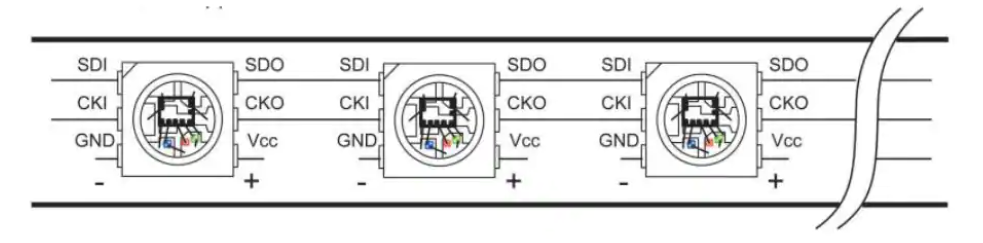
### Daisy chain connection of APA102 LEDs

The 10-LED PCB board has 4 wired connections: DATA CLK, PWR, GROUND.\
The DATA line(wire) of the board connects to the Data\_in of the first LED.\
Each LED is daisy chained to the next from Data\_out pin of one to Data\_IN of the next, and so on.

<figure><img src="/files/37ouxrv7tyrJoyUck5lL" alt=""><figcaption><p>SDI = Data_IN<br>APA102 LEDs connect in a daisy chain manner</p></figcaption></figure>

{% hint style="info" %}
There are other APA102 LED boards that might be used. For example there are 3-LED boards also on El Mandadero. These ***boards*** can also daisy chain from one board to the next. From the software point of view these are just considered one long string of LEDs.
{% endhint %}

<figure><img src="/files/kKOIMb8qB41xIjnMM6zg" alt=""><figcaption><p>ELM-6D0-001 board</p></figcaption></figure>

## Connecting the LED board to the UCAN board.

The 10-LED "headlight board" shown here is built from an American standard taillight. The internal board has been changed from a simple "on-bright, on-dim" direct DC wiring to the digital connection to these RGB LEDs. Therefore an extra black wire was added to the plastic assembly.

<table><thead><tr><th width="209">10-LED  "Headlight"</th><th width="116.33333333333331">Signal</th><th width="155">SPI Port (P1) Pin</th><th>UCAN Jumper wire color </th></tr></thead><tbody><tr><td>Black (original Wire)</td><td>PWR (5V)</td><td>SPI pin 1* or <br>P11 'BEC PWR'</td><td><mark style="color:red;"><strong>Red</strong></mark> </td></tr><tr><td><mark style="color:red;">Red</mark></td><td>CLK</td><td>2</td><td><mark style="color:yellow;"><strong>Yellow</strong></mark></td></tr><tr><td>Black (Added wire)</td><td>MOSI</td><td>4</td><td><mark style="color:orange;"><strong>Orange</strong></mark></td></tr><tr><td>White</td><td>GND</td><td>7</td><td><strong>Black</strong></td></tr></tbody></table>

Arbitrary colored jumper wires were used to connect between the 10=LED headlight board and the  SPI port pin header on the UCAN board. The colors used on the UCAN side were as follows:

| Jumper wire color                             | UCAN/SPIRole |
| --------------------------------------------- | ------------ |
| **Black**                                     | GND          |
| <mark style="color:red;">**Red**</mark>       | Power 5V     |
| <mark style="color:yellow;">**Yellow**</mark> | Clock        |
| <mark style="color:orange;">**Orange**</mark> | MOSI (Data)  |

The wires on the UCAN board are shown connected in the following image:

<figure><img src="/files/VTzRbI6PBjWVPbIs70Di" alt=""><figcaption><p>Wires connection to UCAN board</p></figcaption></figure>

NOTE that the color codes above are non-standard. They should be checked when any different LED boards are being connected.

NOTE that the power 5V may also PREFERRABLY be supplied by using the servo 5V output and providing external 5V power from the BEC header (BEC = 5V DCDC converter)\
See below for board reference:<br>

<figure><img src="/files/IYqrpFgsOVW0ahZe8VUP" alt=""><figcaption></figcaption></figure>

## Software procedure

### NavQPlus software

Connect to NavQPlus via a serial console or though ssh over Ethernet or Wifi.  \
(See NavQPlus gitbook documentation for more details) &#x20;

#### CAN tools

Ensure can-utils and Python are installed on NavQPlus, if not, install the required packages:

```
sudo apt-get update 
sudo apt-get dist-upgrade 
sudo apt-get install can-utils 
pip install python-can 
```

#### Configure CAN bus

Then, reset and configure the NavQPlus CAN bus interfaces:

```
pkill python3 
sudo ip link set can1 down 
sudo ip link set can0 down 
sudo ip link set can0 up type can bitrate 1000000 loopback off restart-ms 100 
sudo ip link set can1 up type can bitrate 1000000 dbitrate 4000000 loopback off fd on fd-non-iso off restart-ms 100 
```

#### ROS2 setup

If not already installed, Install ros2\_orchestrator ROS packages from GitHub.

{% hint style="info" %}
You need to set up your ssh keys for GitHub. If you want to use your token, just change the ssh URLs to HTTPS URLs.
{% endhint %}

```
mkdir -p ~/git/ros2/src 
cd ~/git/ros2/src 
git clone git@github.com:rudislabs/ros2_orchestrator.git 
```

\<todo: change links from rudislabs to NXP>

Build the package:

```
colcon build --symlink-install 
```

run the following command in a bash terminal to automatically set up your ROS environment at startup of a bash terminal:

```
sudo echo "source /home/$USER/git/ros2/install/setup.bash" >> ~/.bashrc
```

Then source your bashrc to ensure it is effective in the current session.

```
source ~/.bashrc 
```

Now, run the following ROS command. It will install dependent packages:

```
ros2 launch ros2_orchestrator orchestrate.launch.py 
```

After it runs re-source your bashrc and re-run the same launch script:

```
ros2 launch ros2_orchestrator orchestrate.launch.py 
```

Open a second ssh session, and run the joy node to begin the connection with the joystick:

```
ros2 run joy joy_node 
```

### Operation of the demo

Now your LEDs are ON and you should be able to control the light intensity.

<figure><img src="/files/LmXIywZIQVrr3CJvzuMx" alt=""><figcaption></figcaption></figure>

Use the left and right buttons of the joystick (buttons in front of the device - see picture below) to play with the colors.<br>

<figure><img src="/files/fr6ro5nwm4Jdf8ntcmAG" alt=""><figcaption></figcaption></figure>


---

# Agent Instructions: Querying This Documentation

If you need additional information that is not directly available in this page, you can query the documentation dynamically by asking a question.

Perform an HTTP GET request on the current page URL with the `ask` query parameter:

```
GET https://nxp.gitbook.io/ucans32k1/ucans32k1sic-demo-application/demo-apa102-rgb-led-control-via-ucans32k146-using-logitech-f310.md?ask=<question>
```

The question should be specific, self-contained, and written in natural language.
The response will contain a direct answer to the question and relevant excerpts and sources from the documentation.

Use this mechanism when the answer is not explicitly present in the current page, you need clarification or additional context, or you want to retrieve related documentation sections.
