> For the complete documentation index, see [llms.txt](https://nxp.gitbook.io/mr-canhubk344/llms.txt). Markdown versions of documentation pages are available by appending `.md` to page URLs; this page is available as [Markdown](https://nxp.gitbook.io/mr-canhubk344/hardware/connectors-and-user-i-o/programming-interface.md).
# Programming Interface
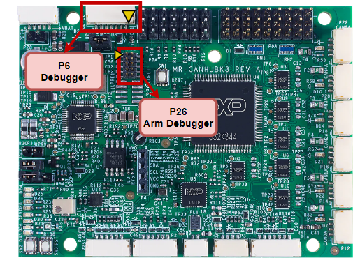
Two programming connectors are provided. The traditional Arm 10-pin JTAG/SWD and a “DCD-LZ” Dronecode Debug connector. Note also that the 10-Pin JTAG/SWD may be removed and replaced with a larger 20-pin header, giving full access to the trace debug pins.
## Location of Debug Connectors
## Debug Connectors
### P6 - DCD-LZ
This is a JST-GH connector from DroneCode Standard which combines the SWD and Console UART into a single connector. The -LZ version of the spec also adds an RST pin.
### P26 - Arm 10-pin JTAG/SWD
This is a 10-pin 0.50”-spacing JTAG/SWD header with the common pinout used by standard Arm debuggers. Ensure pin 1 on the PCB silkscreen is aligned with pin 1 on the debugger.