
BACKUP Copy of Step 3a: Wiring MR-CANHUBK344
Wiring instructions will be demonstrated using images and GIFs for clearer visualization of the process.
RGB LED wiring
You need to have mounted first the LED lights and covers. This step has been explained in this section: #assemble-led-light-and-covers
First, we'll show hot to connect the LEDs cables from the LEDs panels to the PDB and the MR-CANHUBK344.

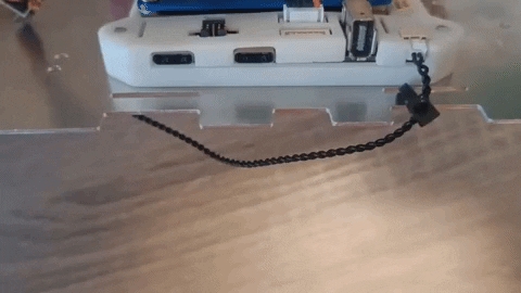
Use the 4-pin cable with a protective covering to connect from the front to the rear LED assembly ends.
Connect the rear LED to the PDB (Power Distribution Board) and the MR-CANHUBK344.
The following image shows the LED lights setup with the left side representing the rear and the right side indicating the front of the car.

The following images show a zoomed vision of the wiring:


The remaining pin is this one:

That must be connected on the following pin of the MR-CANHUBK344:

If you have correctly followed these steps the wiring setup of the LEDs cables should be finished.
QDEC (Quadrature Decoder) Cable
This cable is crutial for calculating the odometry, speed and direction of the robot car. The cable should look like this:

One end of the cable must be attached to the QDEC out pin on the PDB:

And the other end must be attached to the following pin on the MR-CANHUBK344:

BaseT1 Ethernet wiring between NavQPlus and MR-CANHUBK344
Second, we'll show how to connect the ethernet cable between the NavQPlus and the MR-CANHUBK344.
PWM cable wiring to MR-CANHUBK344
The PWM cables that come from the MR-CANHUBK344 board to the Power Distribution Board should look like this.

Servo cable color code
The cable color code is as follows:
White
PWM
Yellow
Red
+ 5V
Red
Black
(-) GND
Brown
Ensure the cable is oriented so that the white PWM signal is connection the port labelled (S) on the MR-CANHUBK344. This is "inboard" on the PCB. The black ground wire will be closest to the outboard edge of the PCB.
The PWM cable that connects to the servo must be connected to PWM0 of the MR-CANHUBK344 as depicted in the following GIF:

The PWM cables that correspond to the motor throttle (PWM 1) and motor ENB (PWM2) must be connected on the following pins on the PDB:

The other end of the cables must be located in this position of the MR-CANHUBK344:

The following GIF shows the connection of the three cables:

Note that an extension cable is used for the servo PWM. The cable on the servo is the alternative coloring as shown in the table above.
Power cable from PDB to MR-CANHUBK344
The last cable to connect is the EXTRA LONG power cable from the MR-CANHUBK344 to the Power Distribution Board which looks like this. The normal length power cable can be similarly connected to the NavQPlus

This is how it must be connected to the PDB:

And the other end must be connected to this pin on the MR-CANHUBK344

The following picture depicts the connections in an animated way.

M10 GPS connection
This is the M10 GPS


And this is all the cable connections available for now.
Last updated
Was this helpful?